Bicycle operating device

a technology for operating devices and bicycles, applied in the direction of mechanical control devices, cycle equipment, instruments, etc., can solve problems such as difficulty in operation of shifters

Active Publication Date: 2010-06-10
SHIMANO INC
View PDF9 Cites 76 Cited by
  • Summary
  • Abstract
  • Description
  • Claims
  • Application Information

AI Technical Summary

Problems solved by technology

If the shift operating device is attached to the handlebar within the brake lever, then the shifter may be difficult to operate, depending on the shape(s) of the operating member(s) of the shift operating device.

Method used


Image

  • Bicycle operating device
  • Bicycle operating device
  • Bicycle operating device

Examples


second embodiment

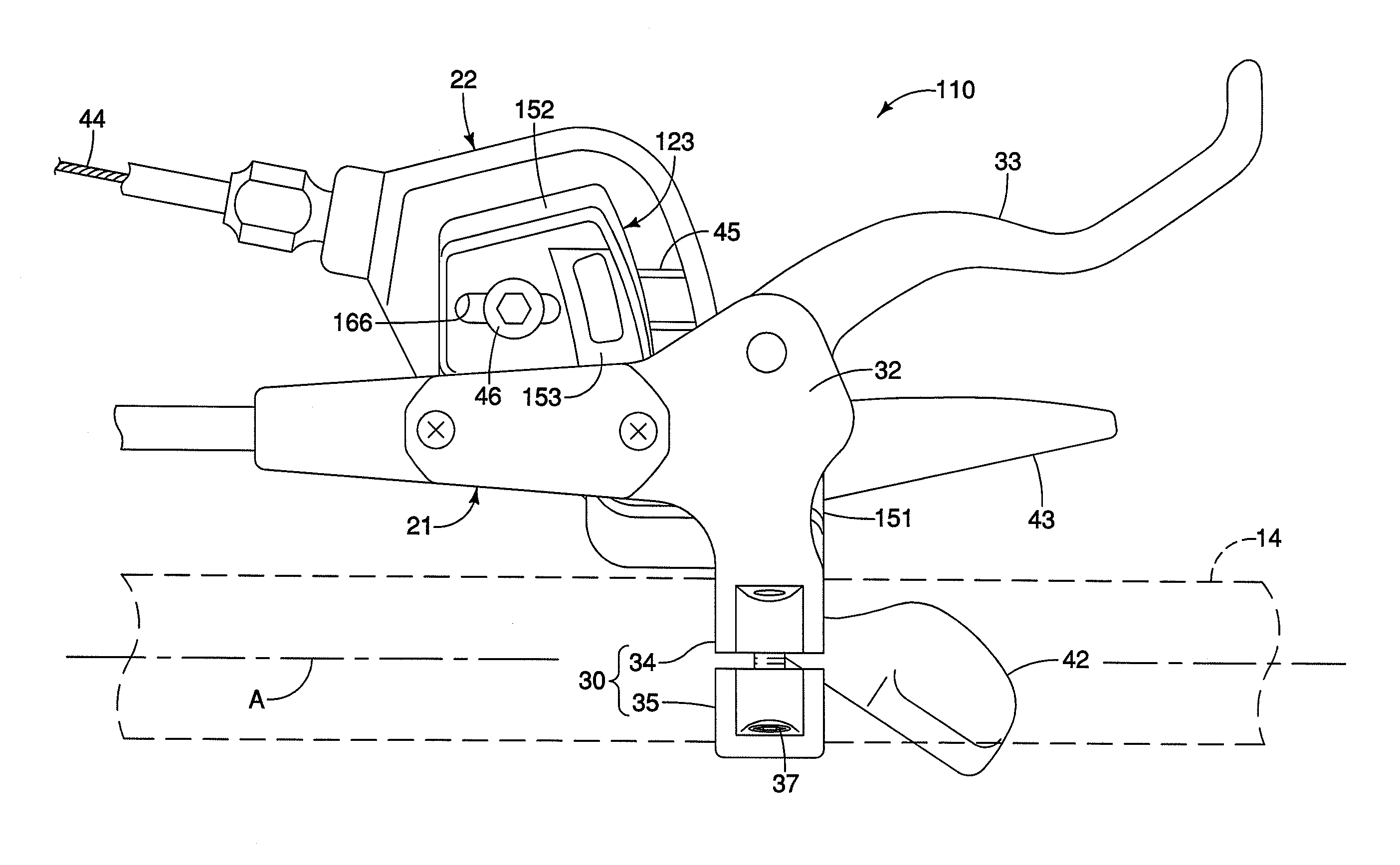
[0054]Referring now to FIGS. 16 to 25, a bicycle operating device 110 in accordance with a second embodiment will now be explained. Basically, the only difference between the bicycle operating device 10 and the bicycle operating device 110 is that the bicycle operating device 110 uses a modified connecting member 123. In view of the similarity between the first and second embodiments, the parts of the second embodiment that are identical to the parts of the first embodiment will be given the same reference numerals as the parts of the first embodiment. Moreover, the descriptions of the parts of the second embodiment that are identical to the parts of the first embodiment may be omitted for the sake of brevity.

[0055]Basically, the connecting member 123 is configured and arranged to change a relative position of the second operating unit 22 with respect to the first operating unit 21 or the handlebar 14 in both the linear direction and the angular direction with respect to the center ...


PUM


Abstract

A bicycle operating device is provided with a first operating unit, a second operating unit and a connecting member. The first operating unit includes a clamp portion for attaching the bicycle operating device to a bicycle and a first operating member. The second operating unit includes a housing and a second operating member. The connecting member includes a first attachment portion and a second attachment portion, with the first attachment portion being detachably attached to an outwardly facing surface of the clamp portion of the first operating unit by an adjustable connection for changing a relative position of the connecting member with respect to the clamp portion. The second attachment portion is detachably attached to the second operating unit.

Description

BACKGROUND OF THE INVENTION[0001]1. Field of the Invention[0002]This invention generally relates to a bicycle operating unit connector. More specifically, the present invention relates to a bicycle operating unit connector that connects a first operating unit to a second operating unit in an adjustable manner.[0003]2. Background Information[0004]Bicycling is becoming an increasingly more popular form of recreation as well as a means of transportation. Moreover, bicycling has become a very popular competitive sport for both amateurs and professionals. Whether the bicycle is used for recreation, transportation or competition, the bicycle industry is constantly improving the various components of the bicycle.[0005]Bicycles are typically provided with a pair of brake levers for operating brake devices that apply braking forces to stop rotation of the wheels. These brake levers are typically mounted on the handlebar by a bracket having band clamp, with one being located adjacent each of ...

Claims


Application Information

Patent Timeline
Patent Type & Authority Applications(United States)
IPC IPC(8): F16C1/10G05G11/00
CPCG05G11/00B60T7/102B62M25/04Y10T74/20287Y10T74/20396Y10T74/20822Y10T403/14B62K23/06Y10T74/20438
Inventor TSUMIYAMA, AKIRA
Owner SHIMANO INC
Why Eureka
Try Eureka