
Flower pot incorporating lights for illuminating plants

a technology for illuminating plants and flowers, applied in the field of flower pots, can solve the problems of reducing the amount of light available in the space, reducing the health benefits of plants, and reducing the use of lighting

Inactive Publication Date: 2010-06-10
INNOVATIVE CONCEPTS
View PDF13 Cites 18 Cited by
  • Summary
  • Abstract
  • Description
  • Claims
  • Application Information

AI Technical Summary

Benefits of technology

[0011]In accordance with the invention, apparatus including structure for illuminating a plant is provided.

Problems solved by technology

Plants may also trap air pollutants, rendering even further healthful effects.
However, modern lifestyles often mean work for long hours and arrival at home long after the sun has fallen.
However, given increasing fuel costs (which, in recent memory goes back certainly as far back as the early 1970s), environmental reasons to reduce consumption of electricity, and so forth, lights put on at night in a space may be task oriented, such as desk lamps or event oriented, such as a lamp on a coffee table which will only illuminate the area surrounded by a group of people talking, for example, at a cocktail party.
There are also other circumstances which may restrict the amount of light available in the space, such as a room or patio, and these may include, for example, low levels of lighting used for economical reasons or to create a certain mood, and sometimes low levels of lighting associated with color lights also intended to create a mood.
Accordingly, plants located on a windowsill, for example, may not be sufficiently illuminated to be visible when lights in a room are turned on.
Likewise, plants located in outdoor planting beds proximate to, for example, an open or closed patio, are not likely to be illuminated by general lighting.
However, placement of such a device in a pot where the plant is already large and dominating the space may be difficult.
Likewise, if there is a need for a wide area of illumination, the positioning of multiple lighting devices within a pot may be problematic.

Method used


Image

  • Flower pot incorporating lights for illuminating plants
  • Flower pot incorporating lights for illuminating plants
  • Flower pot incorporating lights for illuminating plants

Examples


Embodiment Construction

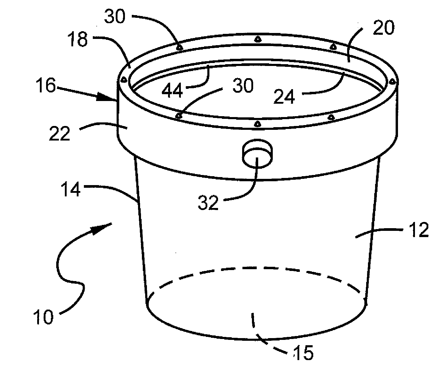
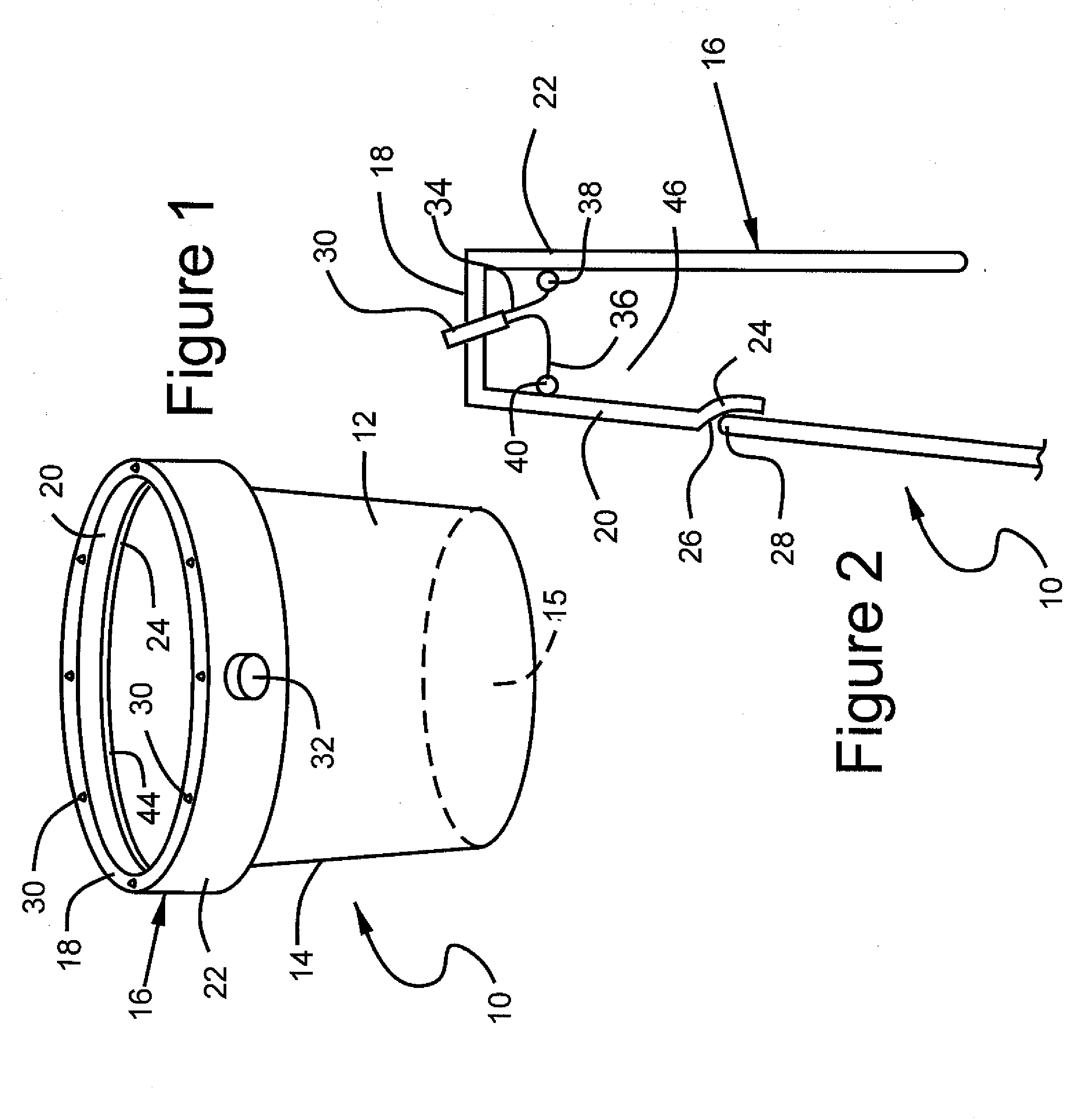
[0046]Referring to FIG. 1, the inventive lighted flowerpot 10 comprises a container 12 with a sidewall 14 and a bottom 15. As can be seen most clearly in FIG. 2, a lighted rim 16 is formed by an upper light supporting surface 18, an inner container engaging sidewall 20 and an outer rim 22. A lip 24 extends from and is formed integrally with inner container engaging sidewall 20.

[0047]Lip 24 defines an inner surface 26 which engages the top 28 of container sidewall 14. Inner surface 26 and top 28 of container sidewall 14 may define a snap fit whereby inner surface 26 and top 28 may be engaged during manufacture and remained together. Alternatively, inner surface 26 and top 28 may be held together using a suitable adhesive.

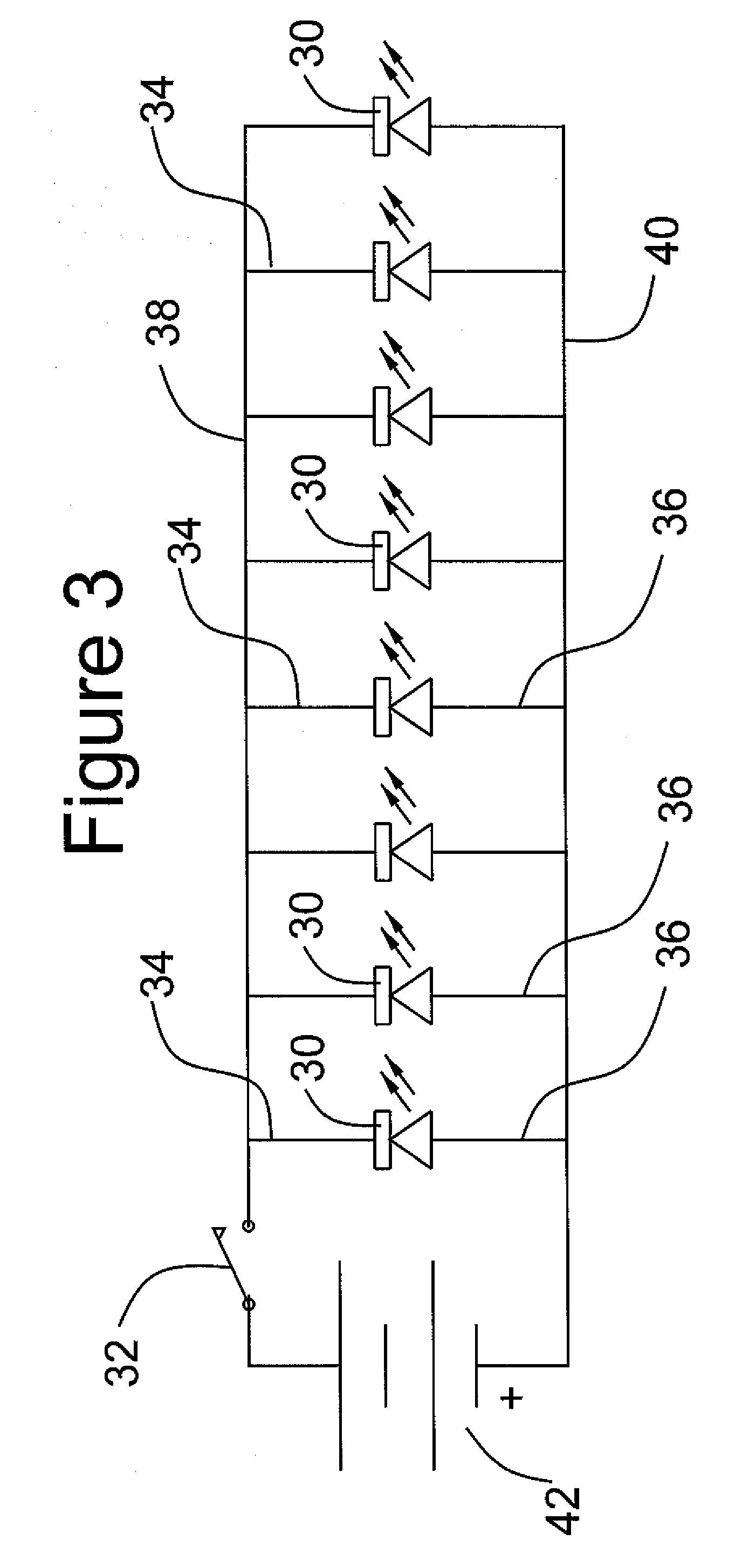
[0048]A plurality of lights 30 is disposed around the upper light supporting surface 18 of rim 16. Lights are turned on and off by a pushbutton switch 32. Lights 30 may comprise light emitting diodes or any suitable light source. Moreover, light emitting diodes 30 ma...


PUM


Abstract

A flowerpot including structure for illuminating a plant or other object or objects contained within the flowerpot may comprise a container. At least one light is supported on the container. A power source is coupled to the at least one light. The container may define an upper circumferential rim. The at least one light may be supported proximate the upper circumferential rim. If desired, a plurality of lights may be disposed at spaced intervals about the circumferential rim.

Description

CROSS REFERENCE TO RELATED APPLICATIONS[0001]This application is a continuation in part of co-pending U.S. patent application Ser. No. 12 / 330,390, filed Dec. 8, 2008 and entitled Light for Illuminating Plants, and U.S. patent application Ser. No. 12 / 236,501, filed Sep. 24, 2008 and entitled Light for Illuminating Plants. The disclosures of these patent applications are hereby incorporated by reference.TECHNICAL FIELD[0002]The invention relates to flower pots including means for illuminating plants, plantings or the like.STATEMENT REGARDING FEDERALLY SPONSORED RESEARCH OR DEVELOPMENT[0003](Not applicable)BACKGROUND OF THE INVENTION[0004]The dramatic effect of illuminated plants is well known. Spotlights are often used to accentuate architectural features, including plants, surrounding trees, and other visual aspects of structural arrangements and features.[0005]Such lights take a wide variety of forms. For example, lights may comprise spotlights. Small area lights, often solar powere...

Claims


Application Information

Patent Timeline
IPC IPC(8): H05B37/02F21V33/00H05B39/02
CPCA01G9/02A01G9/26F21L13/06F21Y2101/02F21V21/0824F21V33/0028F21S9/03F21Y2115/10A01G9/249Y02A40/25
Inventor CANINO, SERAFINOGELORMINO, SCOTT
Owner INNOVATIVE CONCEPTS
Learn More