
Adjustment module

Inactive Publication Date: 2010-06-24
HONG FU JIN PRECISION IND (SHENZHEN) CO LTD +1
View PDF4 Cites 3 Cited by
  • Summary
  • Abstract
  • Description
  • Claims
  • Application Information

AI Technical Summary

Problems solved by technology

However, the sliding member has considerable weight and volume, and the extending portion of the coil spring is relatively long.

Method used


Image

  • Adjustment module
  • Adjustment module
  • Adjustment module

Examples


Embodiment Construction

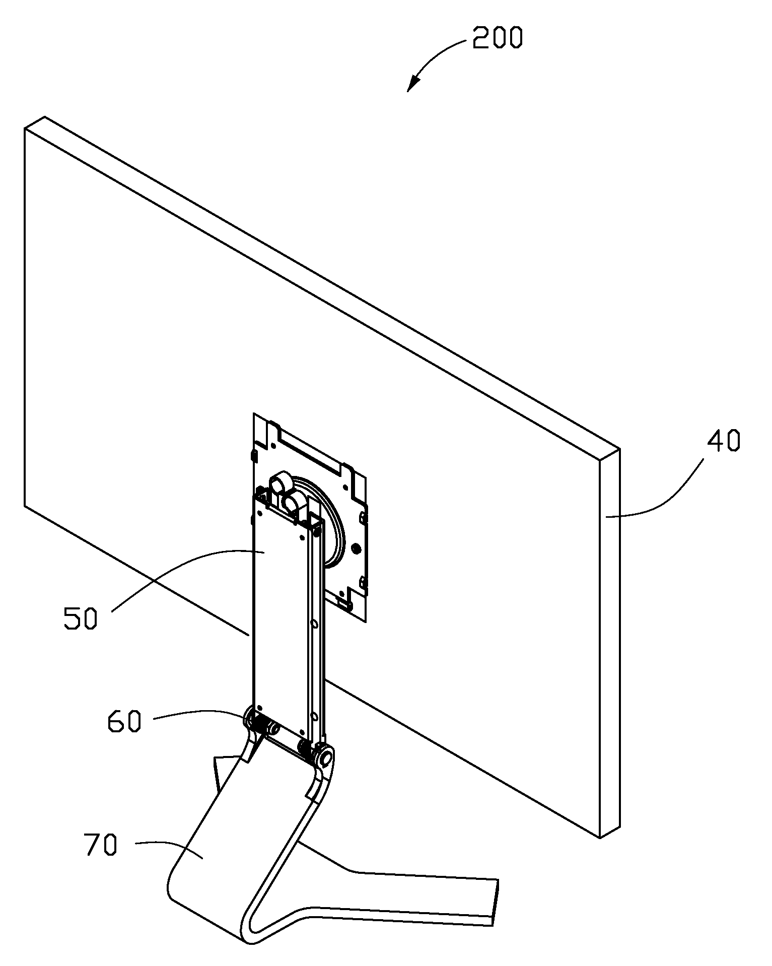
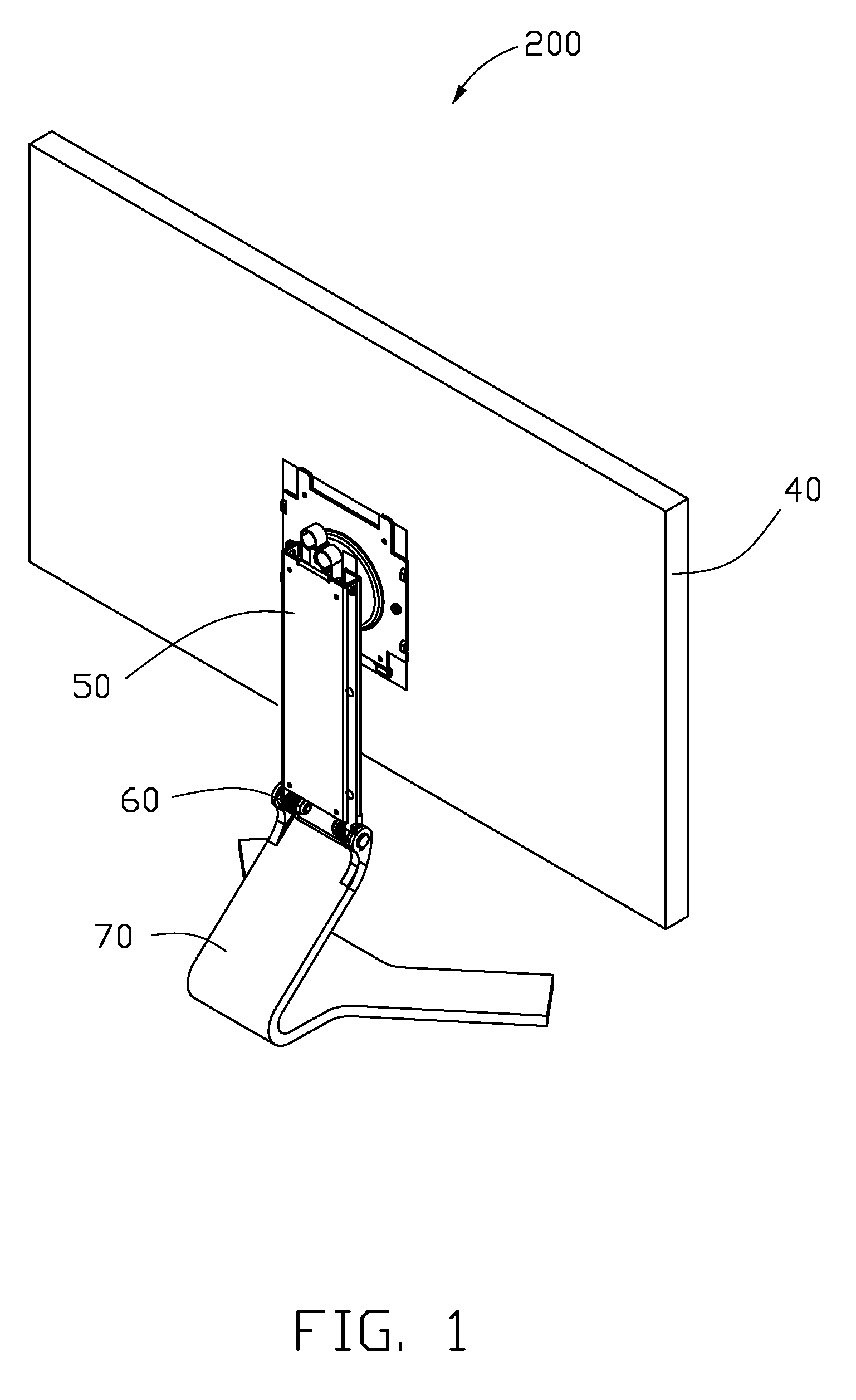
[0016]Referring to FIG. 1, a liquid crystal display 200 includes a display panel 40, an embodiment of an adjustment module 50, a hinge assembly 60, and a base 70. The adjustment module 50 connects the hinge assembly 60 to the display panel 40 and adjusts a distance between the display panel 40 to a supporting surface (not shown) on which the liquid crystal display 200 is situated. The hinge assembly 60 hinges the adjustment module 50 on the base 70.

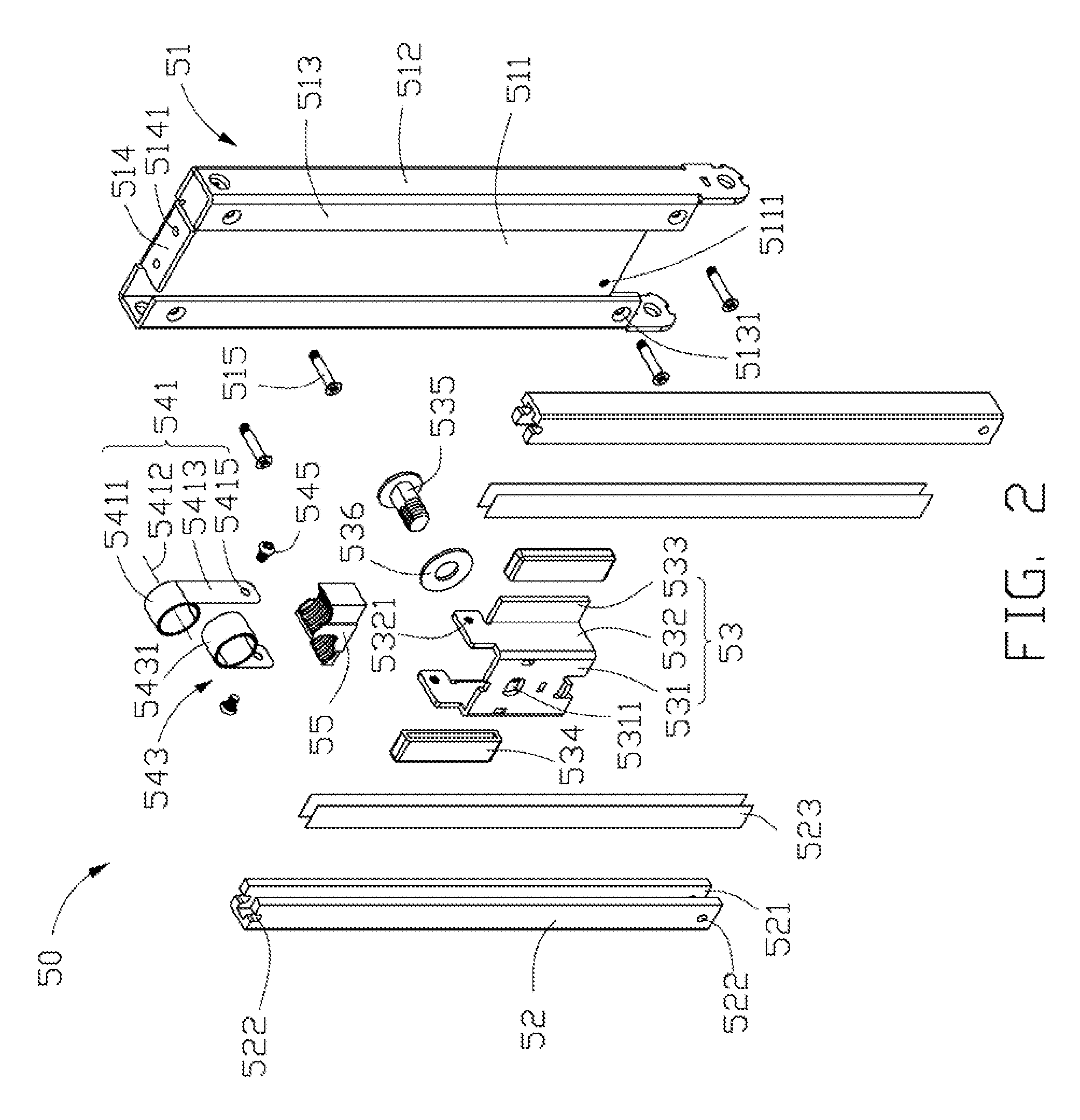
[0017]Referring to FIG. 2, the adjustment module 50 includes a frame 51, a pair of guide rails 52, a sliding member 53, four abrasion resistant sheets 523, two protecting sleeves 534, a shaft 535, a washer 536, a first coiled spring 541, a second coiled spring 543, four first fasteners 515, two second fastener 545, and a supporting member 55.

[0018]The frame 51 may be substantially rectangular, and includes a main plate 511 and two side plates 512 extending from opposite sides of the main plate 511.

[0019]Each side plate 512 forms a limitin...


PUM


Abstract

An adjustment module includes a frame, a sliding member, at least one coiled spring, a pair of guide rails, and a supporting member. The frame includes a main plate. The at least one coiled spring includes an extending portion and a sleeved coiled portion. The guide rails are positioned on opposite sides of the frame. The supporting member is fixed on the frame and has at least one supporting surface. The sliding member is slidably positioned between the guide rails. The coiled portion of the at least one coiled spring is positioned on the at least one supporting surface. An end of the extending portion of the at least one coiled spring is fixed on the sliding member, and an axis of the coiled portion of the at least one coiled spring is substantially perpendicular to the main plate.

Description

BACKGROUND[0001]1. Technical Field[0002]The present disclosure relates to an adjustment module employed in a liquid crystal display.[0003]2. Description of the Related Art[0004]One important feature of widely used liquid crystal displays (LCDs) is flexibility. A display with the display frequently adjusted with respect to the supporting surface via an adjustment module. A commonly used adjustment module employed in an LCD generally includes a base, two guide rails, a sliding member, a shaft, and a coiled spring.[0005]The base generally includes a main plate and two side plates. Two side plates cooperatively define a receiving cavity to receive the coiled spring. The coiled spring includes a coiled portion and an extending portion extending therefrom.[0006]During assembly, the coiled portion is positioned on the shaft, and the shaft is fixed on the base. An end of the extending portion of the coiled spring is fixed on the sliding member. The guide rails are positioned on the side pla...

Claims


Application Information

Patent Timeline
IPC IPC(8): H05K7/02
CPCF16M11/04F16M2200/047F16M11/30F16M11/24
Inventor CHOU, YU-CHENGWANG, JIN-XINDUAN, JUN-WUZHOU, FANLONG, BEN-GUI
Owner HONG FU JIN PRECISION IND (SHENZHEN) CO LTD
Learn More