Light emitting module and LED lamp employing it

a technology of led lamps and light emitting modules, which is applied in the field of illumination devices, can solve the problems of raising a considerable cost burden when the die of the bracket is changed, and achieve the effect of reducing the cost burden

Inactive Publication Date: 2010-07-01
FU ZHUN PRECISION IND SHENZHEN +1
View PDF15 Cites 42 Cited by
  • Summary
  • Abstract
  • Description
  • Claims
  • Application Information

AI Technical Summary

Problems solved by technology

However, a change of the die of the bra

Method used


Image

  • Light emitting module and LED lamp employing it
  • Light emitting module and LED lamp employing it
  • Light emitting module and LED lamp employing it

Examples


Embodiment Construction

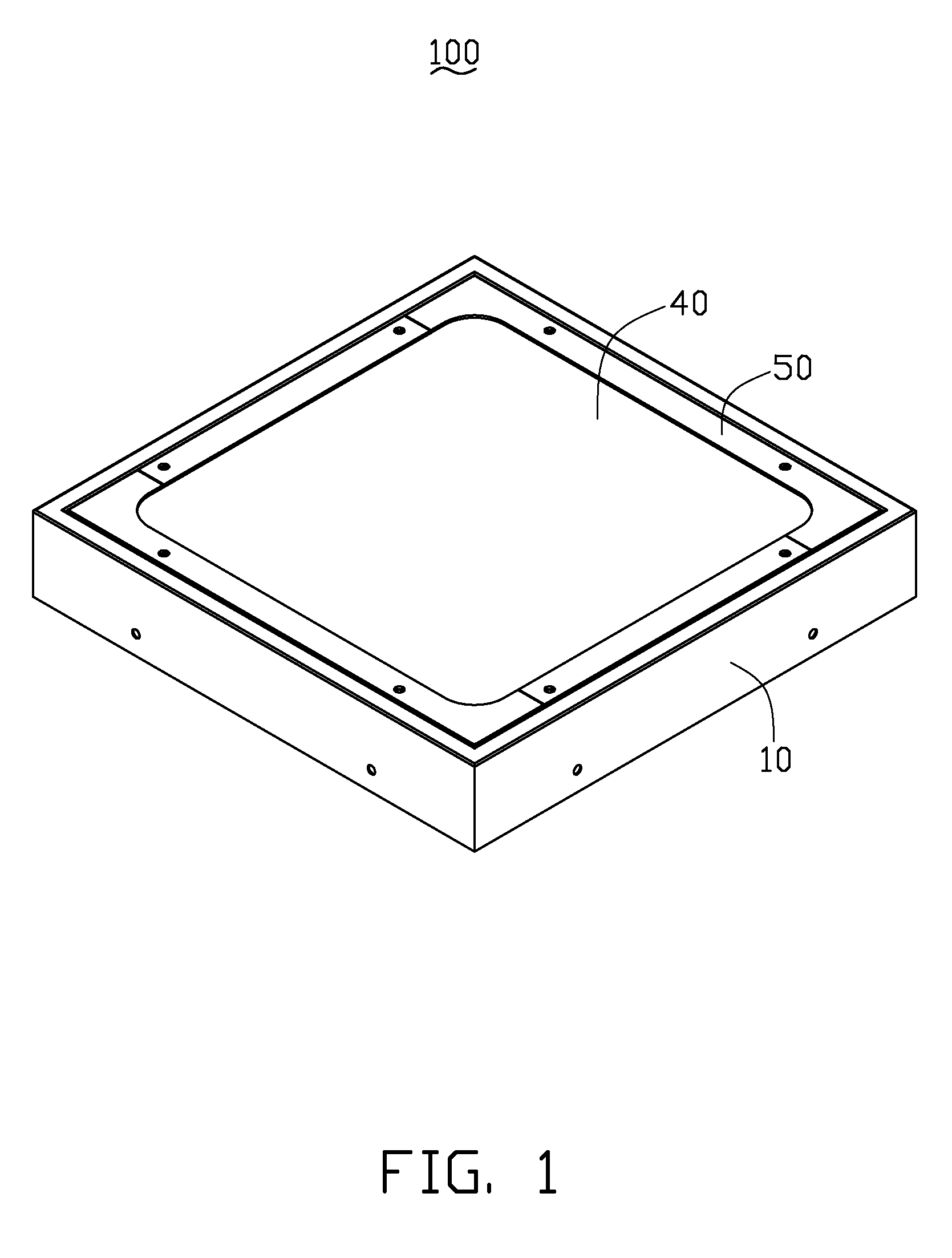
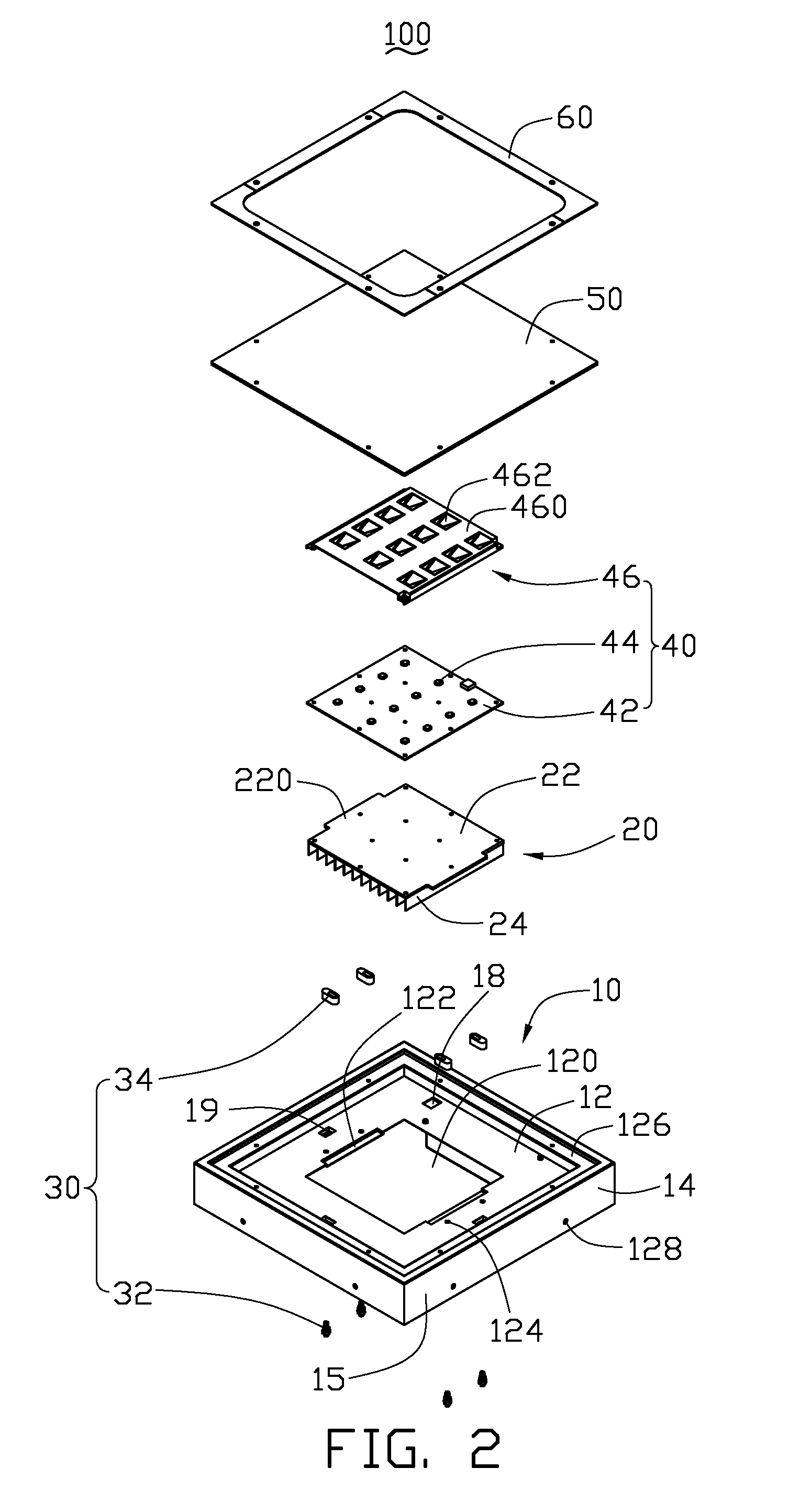
[0014]Referring to FIGS. 1-2, a light emitting module 100 is illustrated in accordance with an embodiment of the disclosure. The light emitting module 100 comprises a grille 10, a heat sink 20, a plurality of fasteners 30 securing the heat sink 20 into a center of the grille 10, an LED module 40 attached to an upper side of the heat sink 20, a transparent plate 50 mounted on a top end of the grille 10 and covering the heat sink 20 and the LED module 40, and an annular pressing portion 60 pressing a peripheral portion of the transparent plate 50 for mounting the transparent plate 50 on the grille 10.

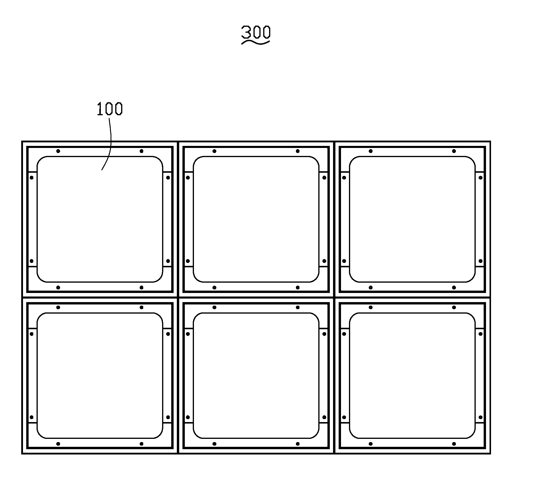
[0015]Referring also to FIG. 3, the shape of the grille 10 is not limited rectangular as shown in this embodiment. The grille 10 can also be triangular, round or other suitable shapes. The grille 10 comprises a plane, flat inner wall 12 and four sidewalls 14 extending upwardly and downwardly from outer edges of the inner wall 12. The sidewalls 14 cooperatively form a rectangular frame 15....


PUM


Abstract

An LED lamp comprises an array of light emitting modules. The light emitting modules each comprise a grille, a heat sink, an LED module and a transparent plate. The grille comprises an inner wall and a frame extending integrally upwards and downwards from the inner wall. The heat sink has a bottom portion thereof extending through the inner wall and has two opposite ends of a top portion thereof abutting the inner wall. The LED module is attached to a top side of the heat sink. The transparent plate is mounted on a top end of the grille and covers the heat sink and the LED module. A plurality of fasteners extend through the inner wall, each having a rotatable resisting portion. The resisting portion presses the heat sink downwardly on the inner wall.

Description

BACKGROUND[0001]1. Technical Field[0002]The disclosure relates to an illuminating device and, more particularly, to a light emitting module and an LED (light emitting diode) lamp using the light emitting module.[0003]2. Description of Related Art[0004]An LED lamp utilizing LEDs as a source of illumination is widely used in many fields because the LEDs have features of long-term reliability, environment friendliness and low power consumption. It is well-known that a conventional grille lamp utilizes fluorescent lights as a source of illumination. With the development of the LED lamp, the LED lamp is intended to be a cost-effective yet high quality replacement for the conventional grille lamp.[0005]Generally, the LED lamp comprises a bracket integrally formed via a die and a plurality of LED modules received in the bracket. The LED lamp can achieve a certain illumination intensity because a dimension of the bracket is certain. For achieving different illumination intensities according...

Claims


Application Information

Patent Timeline
IPC IPC(8): F21V21/00F21V29/00
CPCF21S2/005F21V7/0083F21V19/003F21Y2115/10F21V29/89F21Y2105/10F21V29/76
Inventor WUNG, SHIH-HSUNCHEN, YONG-DONGXU, WEN
Owner FU ZHUN PRECISION IND SHENZHEN
Why Eureka
Try Eureka