Handy cleaners
a technology for cleaning tools and cleaning brushes, which is applied in the field of handy cleaning tools, can solve the problems of troublesome closure of the cover, difficult to achieve the reduction of the size of the handy cleaner, and fear of the cover being los
- Summary
- Abstract
- Description
- Claims
- Application Information
AI Technical Summary
Benefits of technology
Problems solved by technology
Method used
Image

Examples
first embodiment
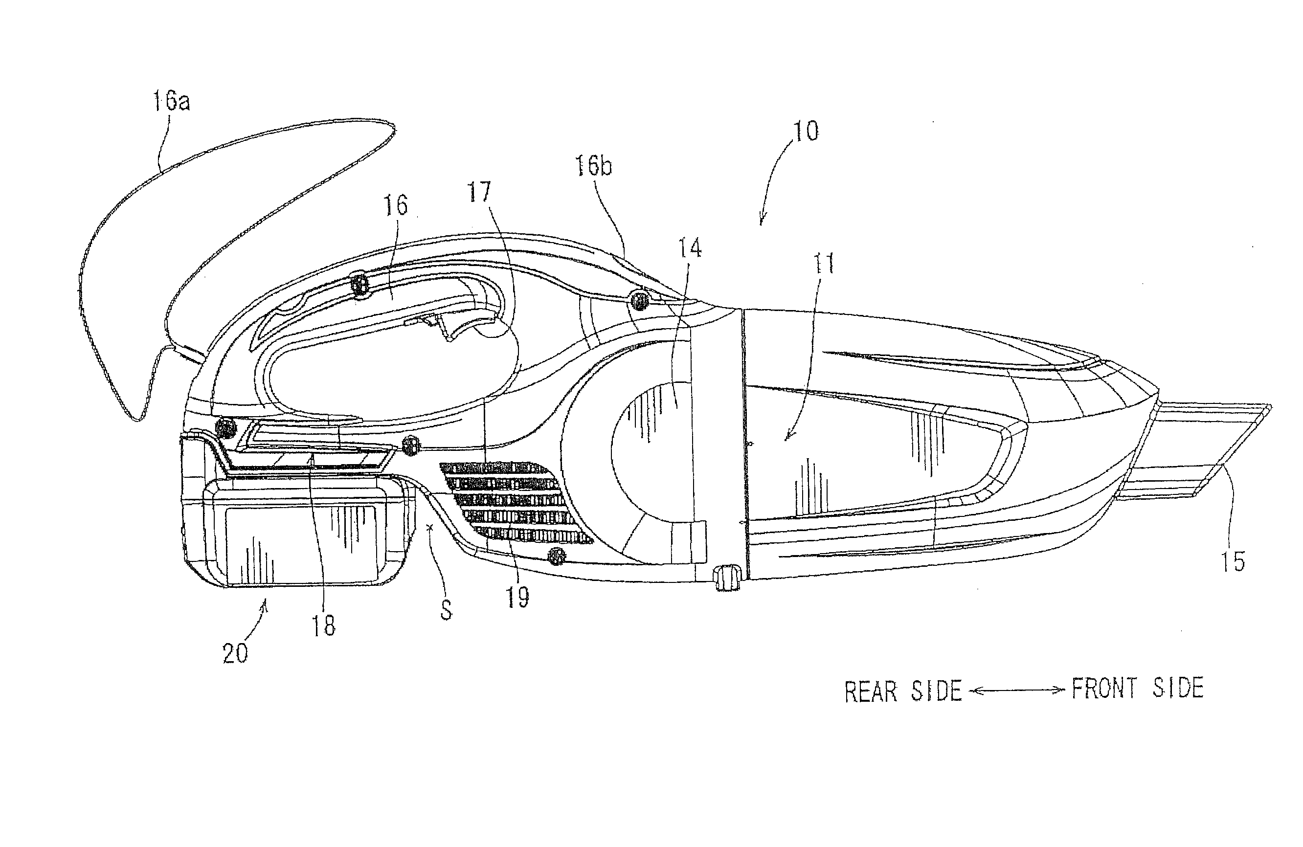
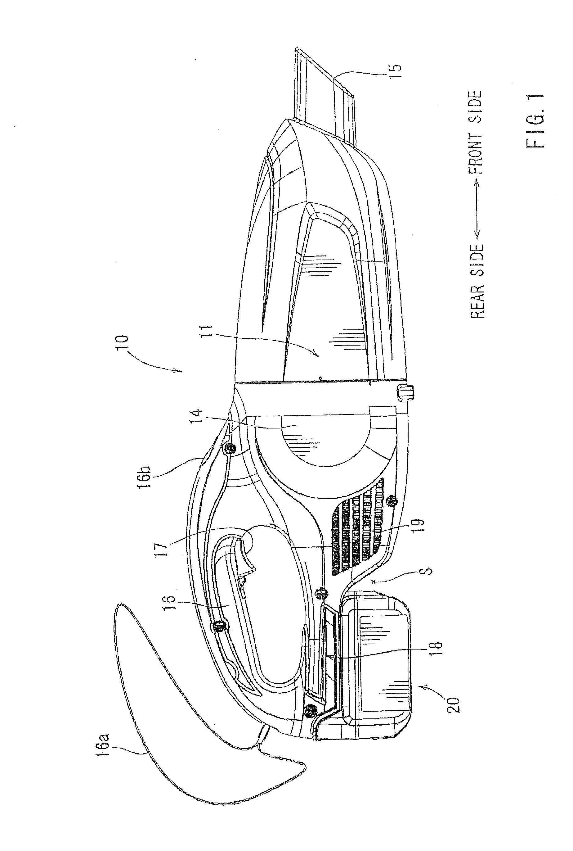
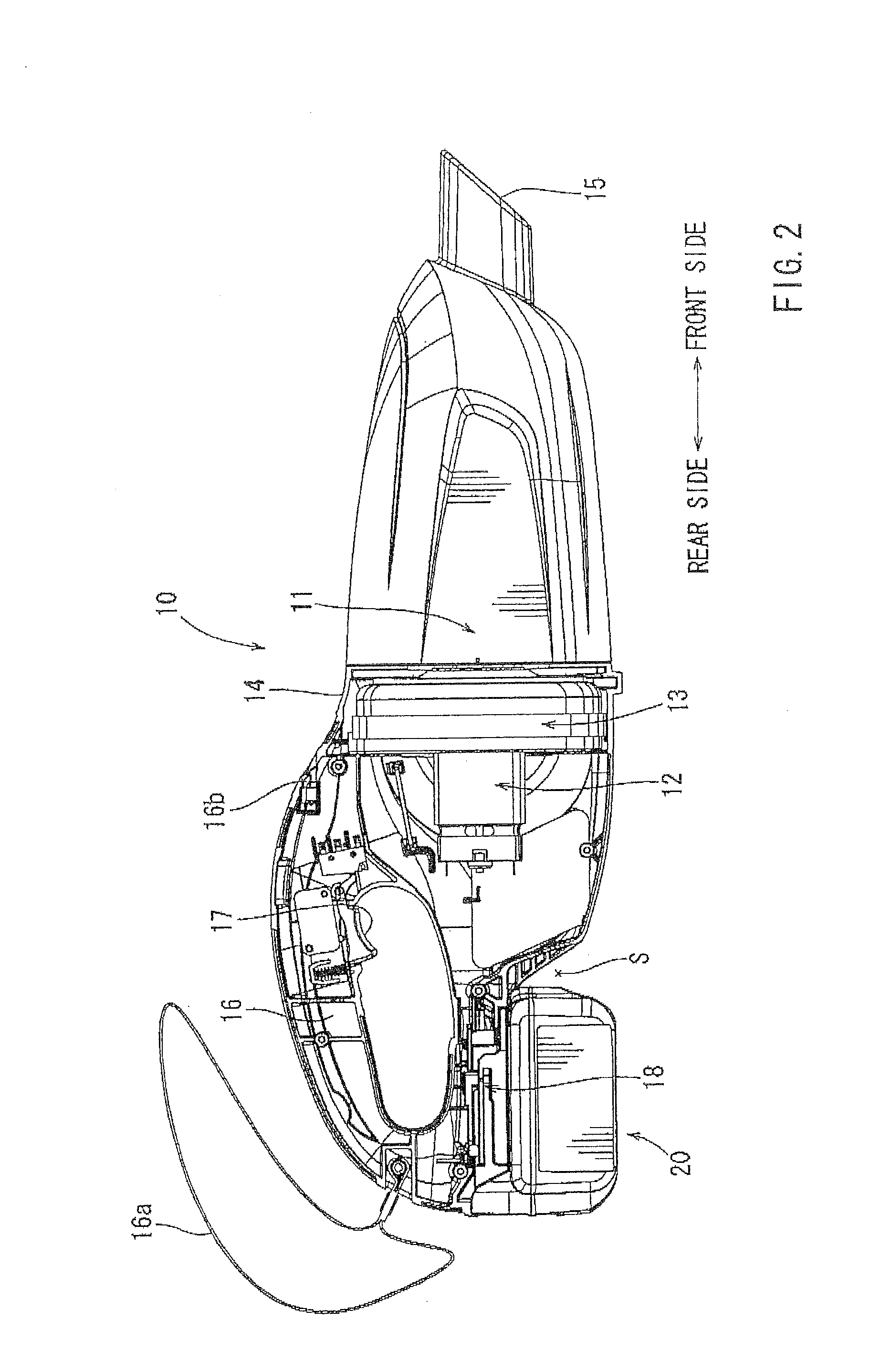
[0046]FIGS. 1 through 3 show the handy cleaner 10 of the first embodiment. The handy cleaner 10 has the battery pack 20 as a power source, which can be repeatedly used by being removed from the cleaner body 11 and recharged. The cleaner body 11 has a body housing 14, in which an electric motor 12 and a suction mechanism 13 are accommodated. The electric motor 12 is driven by an electric power supplied from the battery pack 20. The suction mechanism 13 primarily includes a fan rotatably driven by the electric motor 12. A dust inlet port 15 is provided at the front end portion of the body housing 14. The front half of the body housing 14 can be removed from the rear half for the purpose of disposing of the collected dust.
[0047]At the rear portion of the body housing 14, there is provided a loop-shaped handle 16 that can be grasped by the user. On the inner peripheral side of the handle 16, there is provided a switch lever 17 that can be pulled by a finger of the user. When the switch ...
second embodiment
[0066]Next, FIGS. 6 through 9 show the handy cleaner 30 according to a second embodiment of the present invention. Similar to the first embodiment, a cleaner body 31 of the handy cleaner 30 has a body housing 34, in which an electric motor 32 and a suction mechanism 33 operated by the electric motor are accommodated. A dust inlet port 35 is provided at the front portion of the body housing 34.
[0067]At the rear portion of the cleaner body 31, there is provided a loop-shaped handle 36 that can be grasped by the user. On the inner peripheral side of the handle 36, there is provided a switch lever 37 that can be pulled by a finger(s) of the user. When the switch lever 37 is pulled, the electric motor 32 is started, so that dust or the like can be drawn from the dust inlet port 35.
[0068]In the right and left side portions of the body housing 34 around the suction mechanism 33, there are provided exhaust ports 39. Exhaust gas resulting from the dust drawing operation can be blown out from...
third embodiment
[0075]FIGS. 10 through 13 show the handy cleaner 50 according to the third embodiment of the present invention. The battery pack 60 of the handy cleaner 50 of this embodiment is different from that of the second embodiment described above. The cleaner body 51 has a construction similar to the cleaner body 31 of the second embodiment. Thus, a dust inlet port 55 is provided at the forward end portion of the cleaner body 51, and a loop-shaped handle 56 capable of being grasped by the user is provided on the rear portion of a body housing 54. A switch lover 57 can be pulled by a finger(s) of the user and is provided on the inner peripheral side of the handle 56. Further, in the right and left side portions of the body housing 54 substantially at the center in the longitudinal direction (forward and rearward directions), there are provided exhaust ports 59.
[0076]A battery mounting portion 58 is provided on the handle 56 and extends along the lower portion of the handle 56. Similar to the...
PUM
 Abstract
Description
Claims
Application Information