
Binder fitting

Inactive Publication Date: 2010-08-19
OKAMURA CORP
View PDF8 Cites 6 Cited by
  • Summary
  • Abstract
  • Description
  • Claims
  • Application Information

AI Technical Summary

Problems solved by technology

In the case of the two-hole type binder fitting, it is bothersome to form a pair of holes at the left end portion of the object to be filed, and the object to be filed is damaged due to the holes, and, the insertion and / or removal of the object to be filed is also troublesome.
However, in order to realize a binder fitting to file the object to be filed of greater thickness, it is necessary to enlarge the size of the parallel link mechanism, the lever member and the torsion spring, making it less practical, owing to such as higher production cost.
In the binder fitting, since a pair of the link members have to be controlled so as not to incline from a vertical plane by the guide mechanism that guides the lower ends of a pair of the link members to be movable, the structure of the guide mechanism is complex, increasing production costs.
In addition, since the number of components increase as a whole, a longer base plate and guide mechanism, and a pair of longer link members with great strength and high rigidity are required, enlarging the entire binder fitting, increasing production costs.
In addition, when filing something thick, since a pair of the link members become close to right angles relative to the base plate, it is difficult to generate strong pressing force.

Method used


Image

  • Binder fitting
  • Binder fitting
  • Binder fitting

Examples


embodiment 1

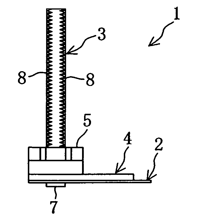
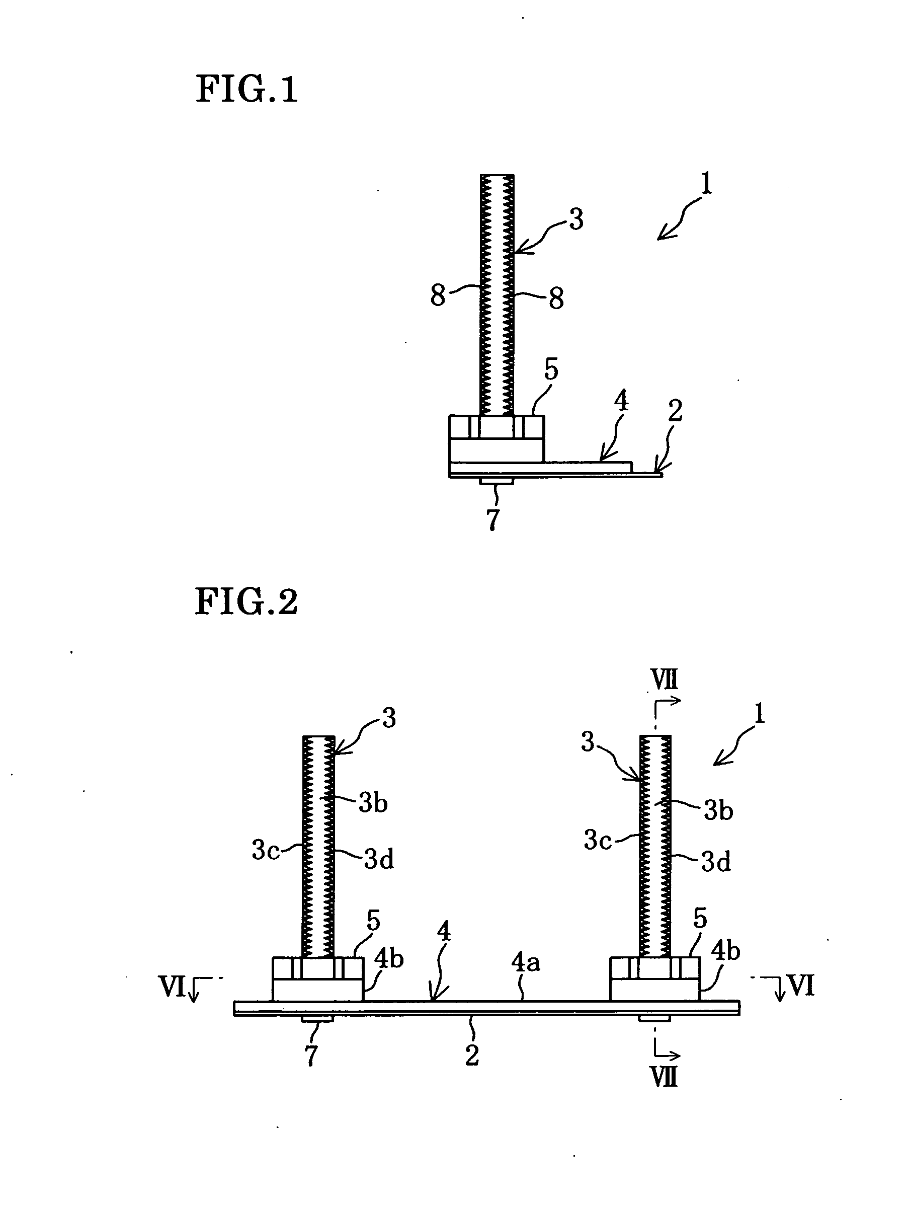
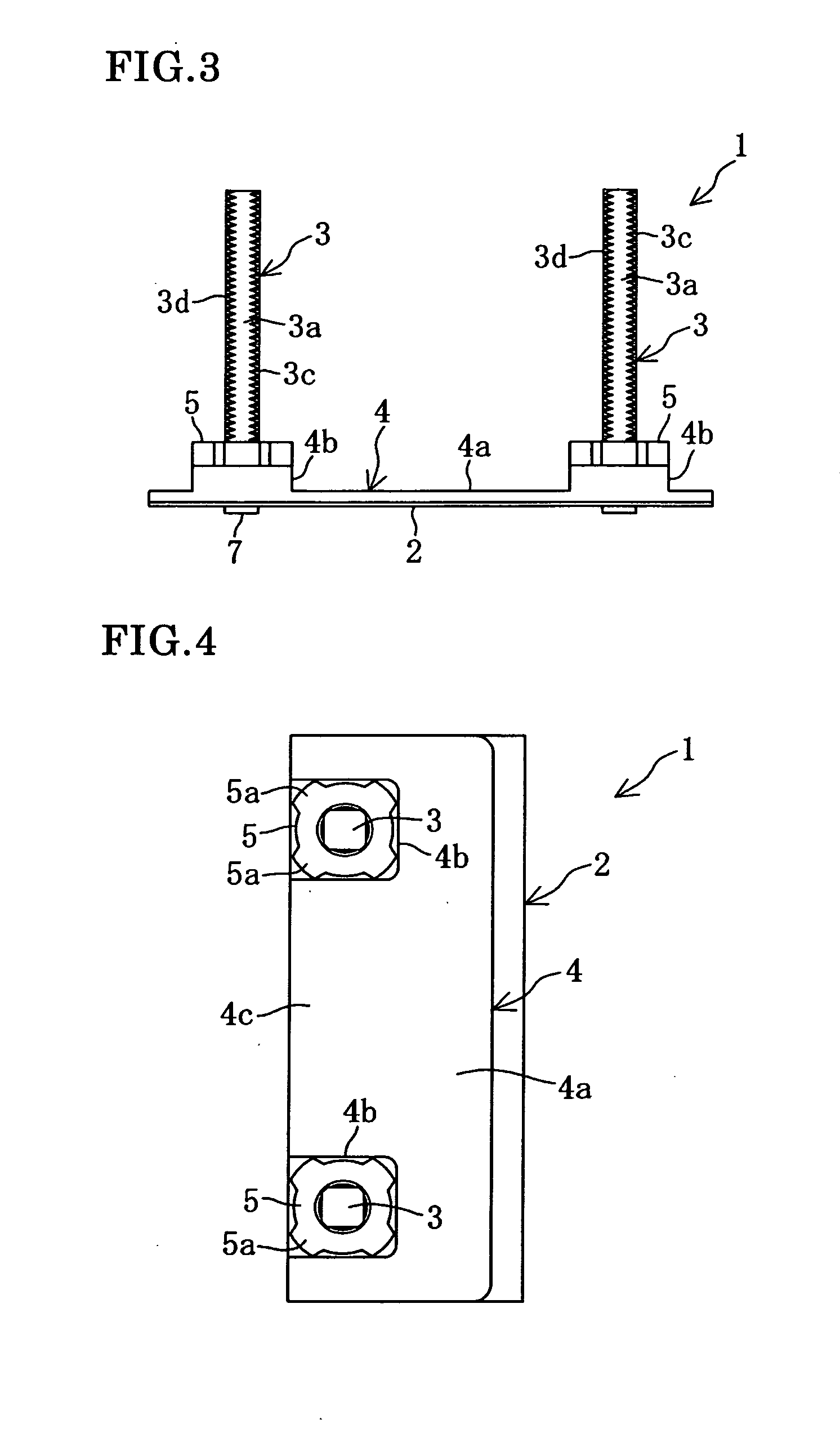
[0044]As shown in FIG. 1 to FIG. 5, although a binder fitting 1 is used by incorporating into a binder having a cover, this binder fitting 1 is solely usable. This binder fitting 1 files an object to be filed P (see FIG. 8) by pressing one end portion. The binder fitting 1 comprises a base plate 2, a pair of rod members 3 vertically fixed on the base plate 2, a press member 4 and a pair of operational nuts 5.

[0045]The base plate 2 is in a horizontal posture when inserting and / or removing the object to be filed P, and the horizontal posture of the base plate 2 (the state in FIG. 4) will be described as the basis for the front / rear direction, the left / right direction and the vertical direction hereafter. A pair of the rod members 3 are vertically fixed on the base plate 2. The press member 4 has a pair of guide holes 9 where a pair of the rod members 3 are inserted to be slidable, and a press surface 10 for pressing the object to be filed P. The press member 4 is vertically movable in...

embodiment 2

[0066]As shown in FIG. 9, in this binder fitting 1A, a pair of press members 4A corresponding to a pair of rod members 3 are arranged as press members. Since the other configurations are similar to those of Embodiment 1, only different configurations will be described. The press members 4A are formed, for example, to be substantially square in a plane view, and the press members 4A have a main body plate 4d and a thick plate 4b, respectively. The size of each press member 4A is, for example, 30 mm×30 mm, and the size of the thick plate 4b is, for example, 17 mm×17 mm. A guide hole, which is similar to the guide hole 9 mentioned above, is formed in each press member 4A.

[0067]Since this press member 4A is small-sized and can be easily moved vertically solely, the slide gaps between the front and rear guide surfaces 3c and 3d of the rod members 3 and the inner wall surface of the guide guide hole 9 may be narrower than the corresponding slide gaps in Embodiment 1. Since a pair of the p...


PUM


Abstract

A binder fitting 1 has a horizontal base plate 2; rod members 3 vertically fixed on the base plate 2; male screws 8 formed in portions of the peripheral surface of each rod member 3; a press member 4, which has guide holes where the rod members 3 are inserted to be slidable, respectively, and a press surface 10 that presses an object to be filed P, and which is vertically movable in parallel due to a guiding effect of the rod members 3 and the guide holes while angles formed with the press surface 10 and the rod members 3 are maintained at right angles, when pressing the object to be filed P; and operational nuts 5, which are screwed together with the screws 8 of the rod members 3, respectively, and which can press and drive the press member 4 toward the base plate 2.

Description

TECHNICAL FIELD[0001]The present invention relates to a binder fitting in which an object to be filed is filed by pressing one end thereof, and particularly relates to a binder fitting that is capable of pressing strongly and easily by effectively using a screw mechanism.BACKGROUND TECHNOLOGY[0002]A two-hole type binder fitting where two rods or two flexible band members are threaded through two holes formed at the end portion of an object to be filed, such as documents, and a press-type binder fitting that presses and clamps an object to be filed without making holes at the end portion of the object to be filed have been available as the binder fitting mounted to a binder. The present invention relates to a press-type (clamp-type) binder fitting.[0003]In the case of the two-hole type binder fitting, it is bothersome to form a pair of holes at the left end portion of the object to be filed, and the object to be filed is damaged due to the holes, and, the insertion and / or removal of ...

Claims


Application Information

Patent Timeline
IPC IPC(8): B42F13/12
CPCB42F1/00B42F13/14B42F9/00
Inventor OKAMURA, TOSHIO
Owner OKAMURA CORP
Learn More