Sealed type rotary compressor

a compressor and sealing technology, applied in the direction of positive displacement liquid engines, liquid fuel engines, lighting and heating apparatus, etc., can solve the problems of short supply of oil to the sliding portions, performance deterioration, etc., to achieve the effect of improving oil separation performance, reducing the amount of oil discharged to the outside of the compressor, and efficient oil separation

Inactive Publication Date: 2010-08-26
SANYO ELECTRIC CO LTD
View PDF15 Cites 3 Cited by
  • Summary
  • Abstract
  • Description
  • Claims
  • Application Information

AI Technical Summary

Benefits of technology

[0013]Furthermore, the outlet of this refrigerant flow path opposite to the rotary compression element side faces the inner wall surface of the sealed container. Therefore, the refrigerant passing through the refrigerant flow path to reach the electromotive element opposite to the rotary compression element side collides with the inner wall surface of the sealed container, diffuses in the space of the electromotive element opposite to the rotary compression element side, and is then discharged to the outside of the sealed container. In this way, the diffusion in the space of the electromotive element opposite to the rotary compression element side further enables separating the oil. In consequence, the oil separation is efficiently performed, and the oil discharged to the outside of the compressor can noticeably be decreased.
[0014]According to the second aspect of the present invention, in addition to the first aspect of the present invention, one of the openings of the discharge pipe which guides the compressed refrigerant in the sealed container to the outside therefrom is directed to the inside of the ring-shaped refrigerant flow path in the sealed container, whereby the compressed refrigerant which has reached the electromotive element opposite to the rotary compression element side through the refrigerant flow path can be inhibited from directly reaching the discharge pipe. In consequence, an oil separation performance can be improved.
[0015]According to the third aspect of the present invention, in addition to the second aspect of the present invention, the distance between the end surface of the rotor opposite to the rotary compression element side and the inner wall surface of the sealed container in the direction of the rotary shaft is 25 mm or more. In consequence, the oil separation space of the electromotive element opposite to the rotary compression element side is sufficiently secured, and the oil separation performance can further be improved.

Problems solved by technology

However, in such a conventional sealed type rotary compressor, the refrigerant gas and the oil cannot sufficiently be separated in the sealed container, and the amount of the oil discharged through the discharge pipe is large, which causes problems that performance deteriorates owing to the outflow of the oil to an external circuit and that the oil supplied to the sliding portions runs short.

Method used


Image

  • Sealed type rotary compressor
  • Sealed type rotary compressor
  • Sealed type rotary compressor

Examples


Embodiment Construction

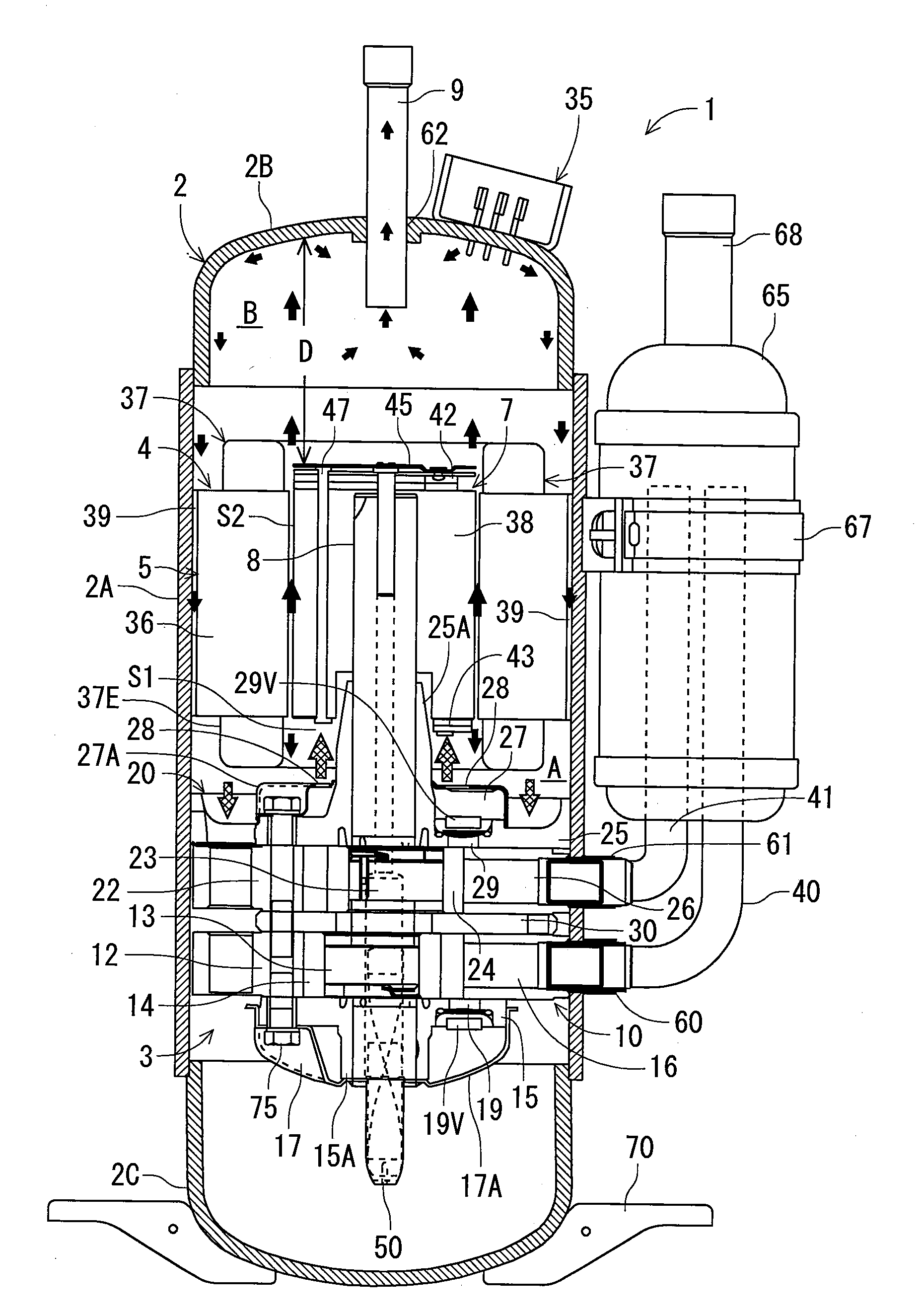
[0022]Hereinafter, an embodiment of a sealed type rotary compressor of the present invention will be described in detail with reference to the drawings. FIG. 1 is a diagram schematically showing the vertically sectional side surface of an internal high pressure type rotary compressor 1 including first and second rotary compression elements as one embodiment of the sealed type rotary compressor to which the present invention is applied.

[0023]The rotary compressor 1 of the present embodiment is a two-cylinder sealed type rotary compressor in which a rotary compression mechanism 3 including first and second rotary compression elements 10, 20 is received in the lower part of the internal space of a vertically cylindrical sealed container 2 formed of a steel plate and in which an electromotive element 4 is received above the rotary compression mechanism.

[0024]The sealed container 2 is constituted of a container main body 2A in which the electromotive element 4 and the first and second ro...


PUM


Abstract

An object of the present invention is to promote oil separation in a sealed container, thereby decreasing the amount of oil discharged to the outside of a compressor. The compressor comprises discharge hole provided at positions facing the end surface of a rotor and through which a compressed refrigerant from first and second rotary compression elements is discharged into the sealed container; and a refrigerant flow path which is extended from a space surrounded with a coil end of a stator projecting from the end surface of the rotor to a rotary compression mechanism side to a space of an air gap between the rotor and the stator, to guide the compressed refrigerant discharged through the discharge hole to an electromotive element opposite to the rotary compression mechanism side, and the outlet of this refrigerant flow path opposite to the rotary compression mechanism side faces the inner wall surface of the sealed container.

Description

BACKGROUND OF THE INVENTION[0001]The present invention relates to a sealed type rotary compressor including an electromotive element and a rotary compression element in a sealed container. More particularly, it relates to a sealed type rotary compressor in which a rotary compression element is received in the lower part of a sealed container and in which an electromotive element is received above this rotary compression element, the electromotive element being constituted of a stator, and a rotor rotatably inserted into a magnetic field generated by this stator and fixed to a rotary shaft which also serves as a crank shaft to drive the rotary compression element.[0002]Heretofore, this type of sealed type rotary compressor is constituted of a rotary compression element received in the lower part of a sealed container and an electromotive element received above the rotary compression element. The electromotive element is constituted of a ring-shaped stator attached along the inner per...

Claims


Application Information

Patent Timeline
Patent Type & Authority Applications(United States)
IPC IPC(8): F04C29/02F25B43/02
CPCF04C18/3564F04C29/026F04C23/008F04C23/001F04C18/00F04C29/02
Inventor OGASAWARA, HIROTSUGUNISHIKAWA, TAKAHIROKOGURE, YOSHIHISAARAI, KAZUHIKOYOSHIDA, HIROYUKI
Owner SANYO ELECTRIC CO LTD
Why Eureka
Try Eureka