Torque Controller for Permanent Magnet Synchronous Motor

a synchronous motor and torque controller technology, applied in the direction of motor/generator/converter stopper, dynamo-electric converter control, dynamo-electric gear control, etc., can solve the problem of large ratio of dc voltage drop due to motor resistance and harness resistance (several tens of volts), and the output voltage of the electric power converter may be limited (saturated). problem, to achieve the effect of high torque control

Active Publication Date: 2010-09-16
HITACHI CAR ENG CO LTD
View PDF8 Cites 9 Cited by
  • Summary
  • Abstract
  • Description
  • Claims
  • Application Information

AI Technical Summary

Benefits of technology

[0012]The preferred embodiment of the present invention can provide a vector controller, for a permanent magnet synchronous motor, that can achieve highly precise torque control at quick response even near a point at which the output voltage of an electric power converter is limited (saturated).
[0013]The preferred embodiment of the present invention can also provide a torque controller, for a permanent magnet synchronous motor, that can be applied to both an inexpensive current detecting system and a system from which a position sensor is eliminated.

Problems solved by technology

With motors mounted on vehicles, however, the motor resistance and the resistance of the harness that interconnects the electric power converter and motor are relatively large, so a ratio of a voltage drop due to the motor resistance and harness resistance to the DC voltage (several tens of volts) may become large.
In this case, the output voltage of the electric power converter may be limited (saturated) even in the low-speed range.

Method used


Image

  • Torque Controller for Permanent Magnet Synchronous Motor
  • Torque Controller for Permanent Magnet Synchronous Motor
  • Torque Controller for Permanent Magnet Synchronous Motor

Examples


first embodiment

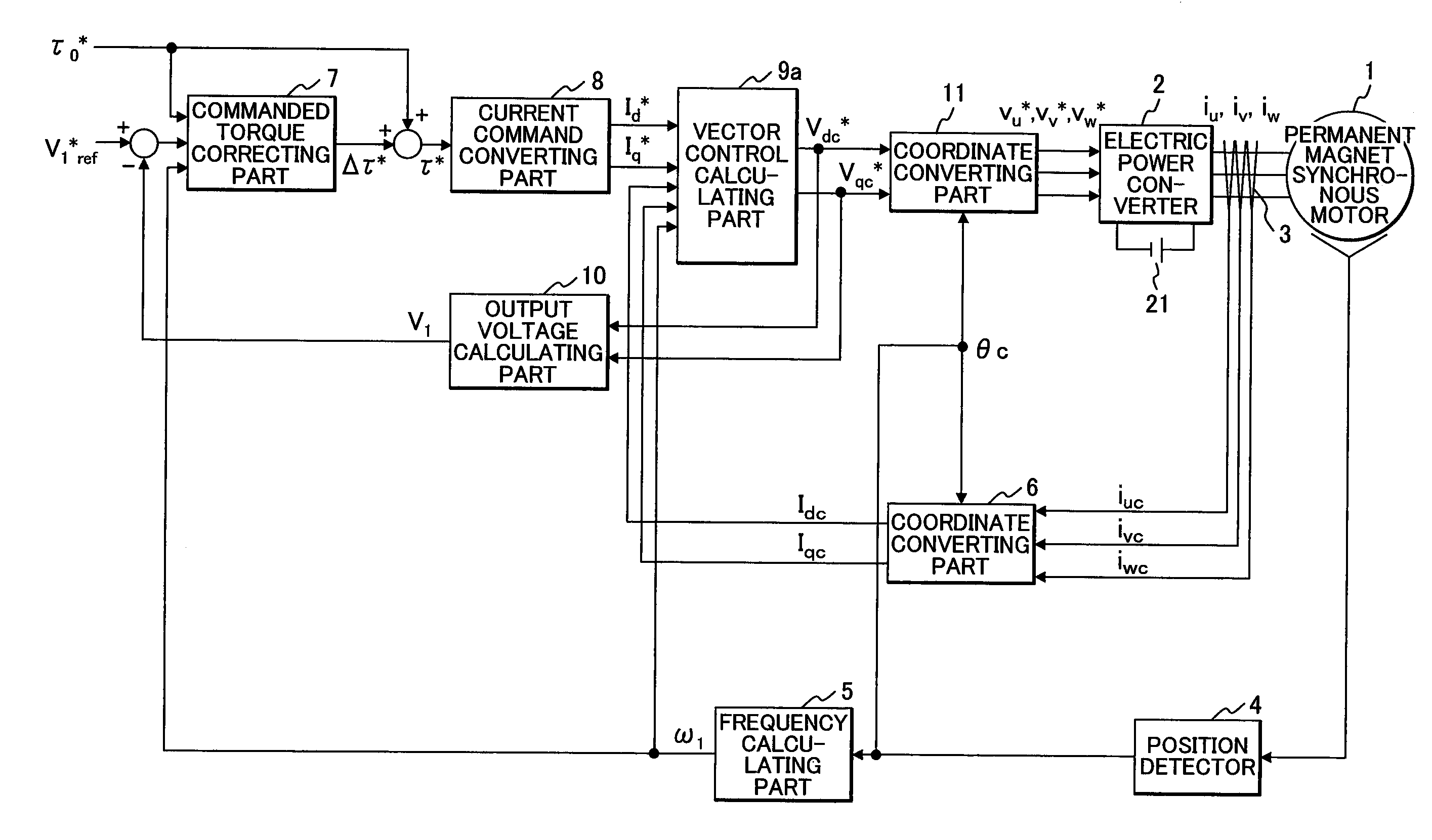
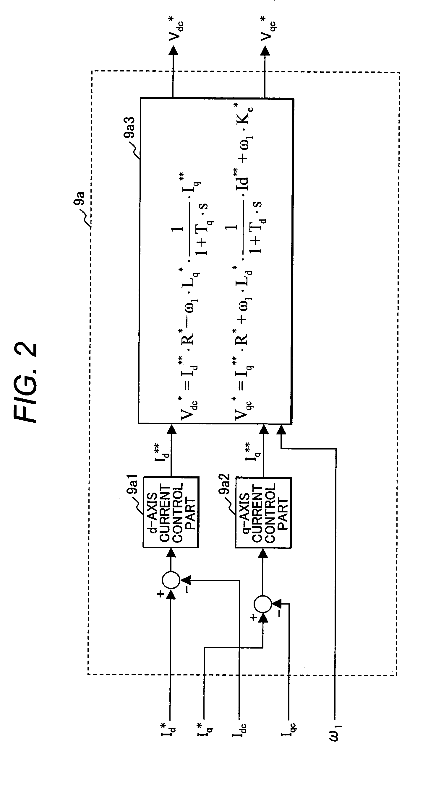
[0026]FIG. 1 is an exemplary block diagram showing the structure of a torque controller for a permanent magnet synchronous motor in a first embodiment of the present invention.

[0027]The main circuit in FIG. 1 includes a permanent magnet synchronous motor 1, an electric power converter 2 that outputs voltages in proportion to commanded three-phase voltages Vu*, Vv*, and Vw*, and a DC power supply 21 that supplies a DC voltage. Sensors included in the main circuit are a current detector 3 that detects three-phase AC currents iu, iv, and iw and a position sensor 4 that detects a position θ of the permanent magnet synchronous motor 1 by using a resolver or an encoder.

[0028]In the functional section, which is a control circuit, a frequency calculating part 5 generates a calculated frequency ω1 from a detected positional value θc; a coordinate converting part 6 outputs detected currents Idc and Iqc for the d-axis and q-axis from detected values iuc, ivc, and iwc of the three-phase AC curr...

second embodiment

[0066]FIG. 8 is a block diagram showing the structure of a torque controller for a permanent magnet synchronous motor in a second embodiment of the present invention.

[0067]This embodiment is applied to a torque controller from which a position sensor such a resolver or an encoder is eliminated. In FIG. 8, the same components as in FIG. 1 are denoted by the same reference characters. An axial error calculating part 12 infers an axial error Δθc (=θc′−θ), which is a difference between an inferred phase value θc′ and motor phase value θ by using the d-axis commanded voltage Vdc*, the q-axis commanded voltage Vqc*, the detected currents Idc and Iqc, an inferred frequency ω1′, and the motor constants, as in equation (14).

[Equation14]Δθc=tan-1[Vdc*-R*·Idc+ω1′·Lq*·IqcVqc*-R*·Iqc-ω1′·Lq*·Idc](14)

[0068]A frequency inferring part 13 calculates the inferred frequency ω1′ so that the calculated axial error Δθc becomes 0. A phase calculating part 14 integrates the inferred frequency ωc′ to calcul...

third embodiment

[0071]Although the expensive current detector 3 is used in the first and second embodiments to detect the three-phase AC currents iu, iv, and iw, the present invention can also be applied to a torque controller that detects currents in an inexpensive manner.

[0072]FIG. 9 shows the structure of a torque controller in a permanent magnet synchronous motor according to a third embodiment of the present invention, the torque controller detecting currents as described above. In FIG. 9, the same components as in FIG. 8 are denoted by the same reference characters. A current inferring part 15 infers the three-phase currents iu, iv, and iw, which flow in the permanent magnet synchronous motor 1, from a DC current IDC flowing in the input bus of the electric power converter 2.

[0073]The coordinate converting part 6 uses inferred currents iû, iv̂, and iŵ to calculate the detected currents Idc and Iqc for the d-axis and q-axis.

[0074]Even in an inexpensive control system of this type, in which a...


PUM


Abstract

When output voltage V1 of an electric power converter reaches a prescribed voltage V1*ref, a difference between V1 and V1*ref is integrated to correct a commanded torque to τo* (τ*=τo*+Δτ).

Description

CLAIM OF PRIORITY[0001]The present application claims priority from Japanese patent application serial No. 2009-058840, filed on Mar. 12, 2009, the content of which is hereby incorporated by reference into this application.FIELD OF THE INVENTION[0002]The present invention relates to a vector control system for a permanent magnet synchronous motor and, more particularly, to a technology for achieving highly stable torque control at quick response even near a point at which the output voltage of an electric power converter is limited (saturated).BACKGROUND OF THE INVENTION[0003]The output voltage of an electric power converter in a controller for controlling current supplied to an AC motor by vector control may be limited (saturated). Prior art applicable to this case is described in, for example, Japanese Patent Laid-open No. 2004-180441. Specifically, to prevent the AC motor from generating an overcurrent, a current command for the q-axis in the d-q coordinate system, which is an or...

Claims


Application Information

Patent Timeline
Patent Type & Authority Applications(United States)
IPC IPC(8): H02P21/14H02P7/285H02P21/22H02P21/00H02P27/04
CPCH02P6/08H02P21/06H02P21/0035H02P21/22
Inventor TOBARI, KAZUAKIAOYAGI, SHIGEHISAOL, KENTARO
Owner HITACHI CAR ENG CO LTD
Why Eureka
Try Eureka