Control method and control device of permanent-magnet type synchronous motor

Active Publication Date: 2005-10-11
HITACHI LTD +1
View PDF6 Cites 15 Cited by
  • Summary
  • Abstract
  • Description
  • Claims
  • Application Information

AI Technical Summary

Benefits of technology

[0008]An object of the present invention is to provide a control method and a control device of a permanent-ma

Problems solved by technology

Therefore, particularly, correspondence to the rapid change of a load becomes impossible and the torque co

Method used


Image

  • Control method and control device of permanent-magnet type synchronous motor
  • Control method and control device of permanent-magnet type synchronous motor
  • Control method and control device of permanent-magnet type synchronous motor

Examples


first embodiment

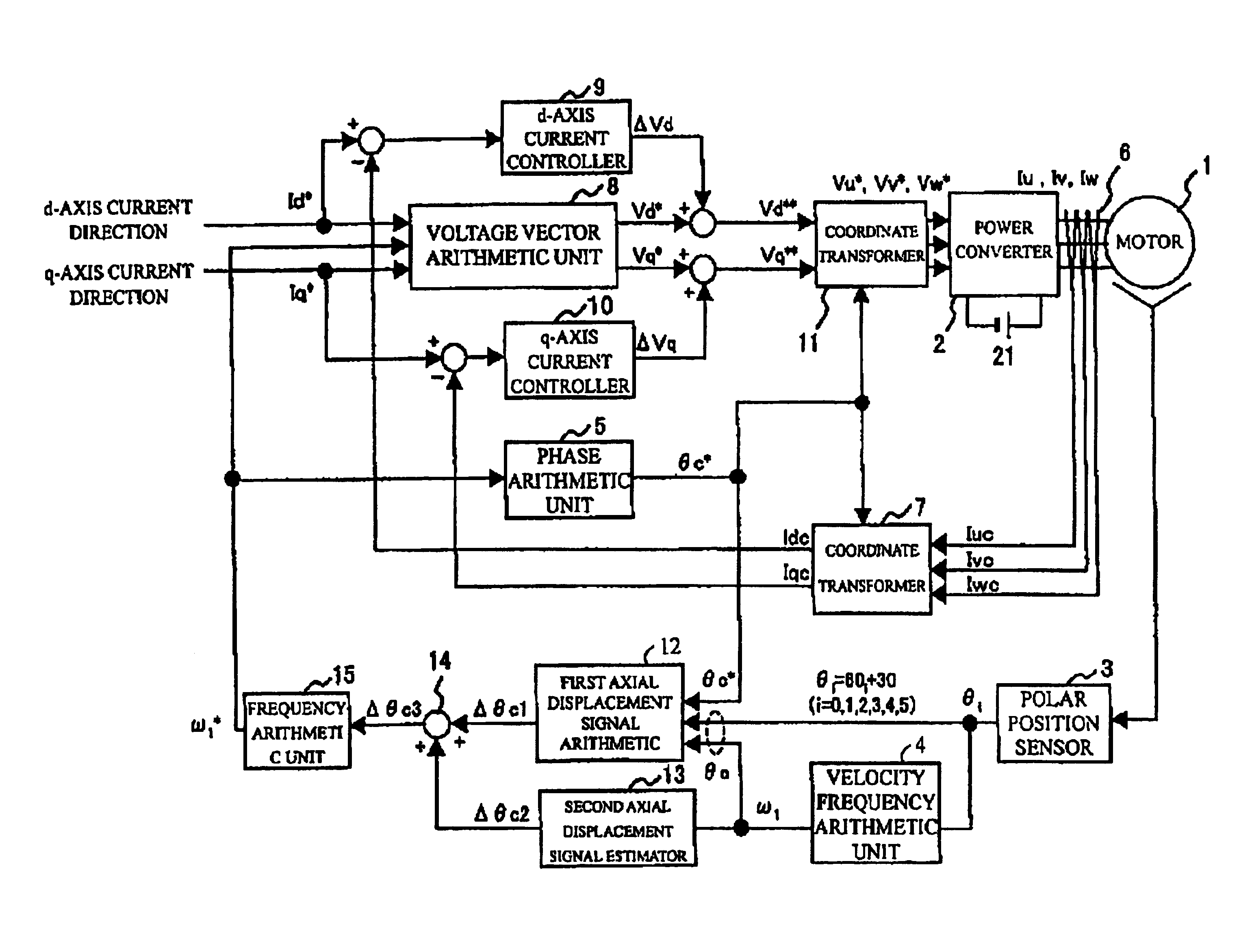
[0027]FIG. 1 is a block diagram showing the configuration of a control device of a permanent-magnet type synchronous motor equivalent to a first embodiment of the invention. The permanent-magnet type synchronous motor 1 is fed three-phase current of variable voltage and a variable frequency from a power converter 2 and is controlled at variable speed. The power converter 2 converts and outputs dc voltage from a direct voltage source 21 to three-phase alternating output voltage proportional to voltage directed values Vu*, Vv*, Vw*. A polar position sensor 3 senses a positional sensed value θi every 60° of electrical angle of the motor 1. A velocity frequency arithmetic unit 4 operates the velocity frequency ω1 of the motor 1 based upon the positional sensed value θi.

[0028]A phase arithmetic unit 5 operates a rotational phase direction θc* to the motor based upon a frequency directed value ω1*. A current sensor 6 senses three-phase currents Iu, Iv, Iw and outputs sensed values Iuc, Iv...

second embodiment

[0074]FIG. 5 is a block diagram showing the configuration of a control device of a permanent-magnet type synchronous motor equivalent to a second embodiment of the invention. The second embodiment is different from the first embodiment in that a second axial displacement signal (Δθc2) estimator 13A to which a q-axis current sensed value Iqc is input is used. In the first embodiment, the velocity frequency ω1 is input to the second axial displacement signal (Δθc2) estimator 13 and the second axial displacement signal Δθc2 is estimated using the control response angular frequency ωcPLL of the frequency arithmetic unit 15. However, in the second embodiment, the motor torque is operated based upon the q-axis current sensed value Ilc, proportional gain is multiplied by the torque operated value, a first-order lag process is executed and a second axial displacement signal Δθc2A is estimated. That is, when load torque τL is small, the similar effect of operation to that in the expression (...

third embodiment

[0078]FIG. 7 is a block diagram showing the configuration of a control device of a permanent-magnet type synchronous motor equivalent to a third embodiment of the invention. This embodiment is different from the first embodiment in configuration for acquiring d-axis and q-axis voltage directions input to a coordinate transformer 11 based upon d-axis and q-axis current directions and the other is completely the same. As shown in FIG. 7, a voltage vector arithmetic unit 8A operates voltage reference values Vd***, Vq*** based upon a motor constant, second current directed values Id**, Iq** and a frequency directed value ω1*. A d-axis current direction arithmetic unit 16 outputs the second d-axis current directed value Id** according to deviation between a d-axis current directed value Id* and its sensed value Idc. Similarly, a q-axis current direction arithmetic unit 17 outputs the second q-axis current directed value Iq** according to deviation between a q-axis current directed value ...


PUM


Abstract

The object of the invention is to inhibit the axial displacement caused by the insufficiency of a control response angular frequency of a frequency arithmetic unit of a synchronous motor and realize high-precision torque control also in acceleration/deceleration. To achieve the object, the axial displacement of the synchronous motor caused by the insufficiency of the control response angular frequency of the frequency arithmetic unit is estimated in consideration of the control response angular frequency and input Δθc3 (=Δθc1+Δθc2) including an estimated value Δθc2 in addition to an axial displacement operated value Δθc1 to the frequency arithmetic unit is acquired. Hereby, even if the frequency arithmetic unit has an insufficient control response angular frequency, the quantity of axial displacement which will be caused by the insufficiency is estimated as a second axial displacement signal Δθc2, is added and input. Therefore, actual axial displacement Δθc1 of the synchronous motor is stable at a value substantially close to zero.

Description

FIELD OF THE INVENTION[0001]The present invention relates to a control method and a control device of a permanent-magnet type synchronous motor and more particularly to a control method and a control device of a permanent-magnet type synchronous motor improved in torque control technique.BACKGROUND OF THE INVENTION[0002]For the control technique of a conventional type permanent-magnet type synchronous motor provided with a polar position sensor, there is a control device disclosed in a patent document 1. The control device utilizes positional information from the polar position sensor for a limiting value of a rotational phase directed value and prevents the loss of synchronism by the rapid change of a load and others.[0003]Besides, in a patent document 2, for a control device without a position sensor of a synchronous motor, technique for calculating axial displacement based upon a current sensed value and a voltage directed value to a power converter and adjusting an output freque...

Claims


Application Information

Patent Timeline
IPC IPC(8): H02P21/14H02P6/14H02P6/18H02P6/08H02P21/00H02P21/06H02P21/36H02P23/14H02P23/28H02P27/04H02P27/06H02P29/00
CPCH02P6/18H02P21/06H02P2207/05
Inventor TOBARI, KAZUAKIENDO, TSUNEHIROSHIRAHAMA, HIDEFUMITAGUCHI, YOSHIYUKIOKUBO, TOMOFUMI
Owner HITACHI LTD
Why Eureka
Try Eureka