Motor control device, and method for correcting torque constant in such motor control device

a technology of motor control and torque constant, which is applied in the direction of electric generator control, dynamo-electric converter control, dynamo-electric gear control, etc., can solve the problems of not always fixed actual torque constant, inability to correct individual differences, so as to reduce the variation of actual torque constant, eliminate the influence of individual motor torque variation, and achieve high-precision torque control

Active Publication Date: 2017-06-08
PANASONIC INTELLECTUAL PROPERTY MANAGEMENT CO LTD
View PDF10 Cites 3 Cited by
  • Summary
  • Abstract
  • Description
  • Claims
  • Application Information

AI Technical Summary

Benefits of technology

[0006]A motor control device of the present invention includes a speed control part for controlling a motor rotation speed, and a torque correction means for suppressing variation in torque constant due to individual differences of motors. This eliminates influence of torque variation in individual motors and thus achieves high-precision torque control.

Problems solved by technology

However, the actual torque constant is not always fixed.
However, the above conventional method can correct the torque constant according to motor specifications, but cannot correct an influence of individual differences, such as variation in motor production and variation in characteristic of electronic components in a drive circuit.

Method used


Image

  • Motor control device, and method for correcting torque constant in such motor control device
  • Motor control device, and method for correcting torque constant in such motor control device
  • Motor control device, and method for correcting torque constant in such motor control device

Examples


first exemplary embodiment

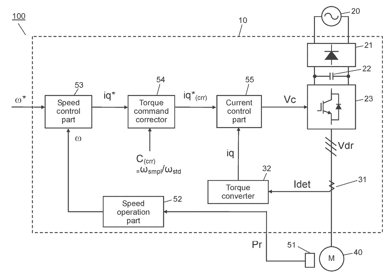
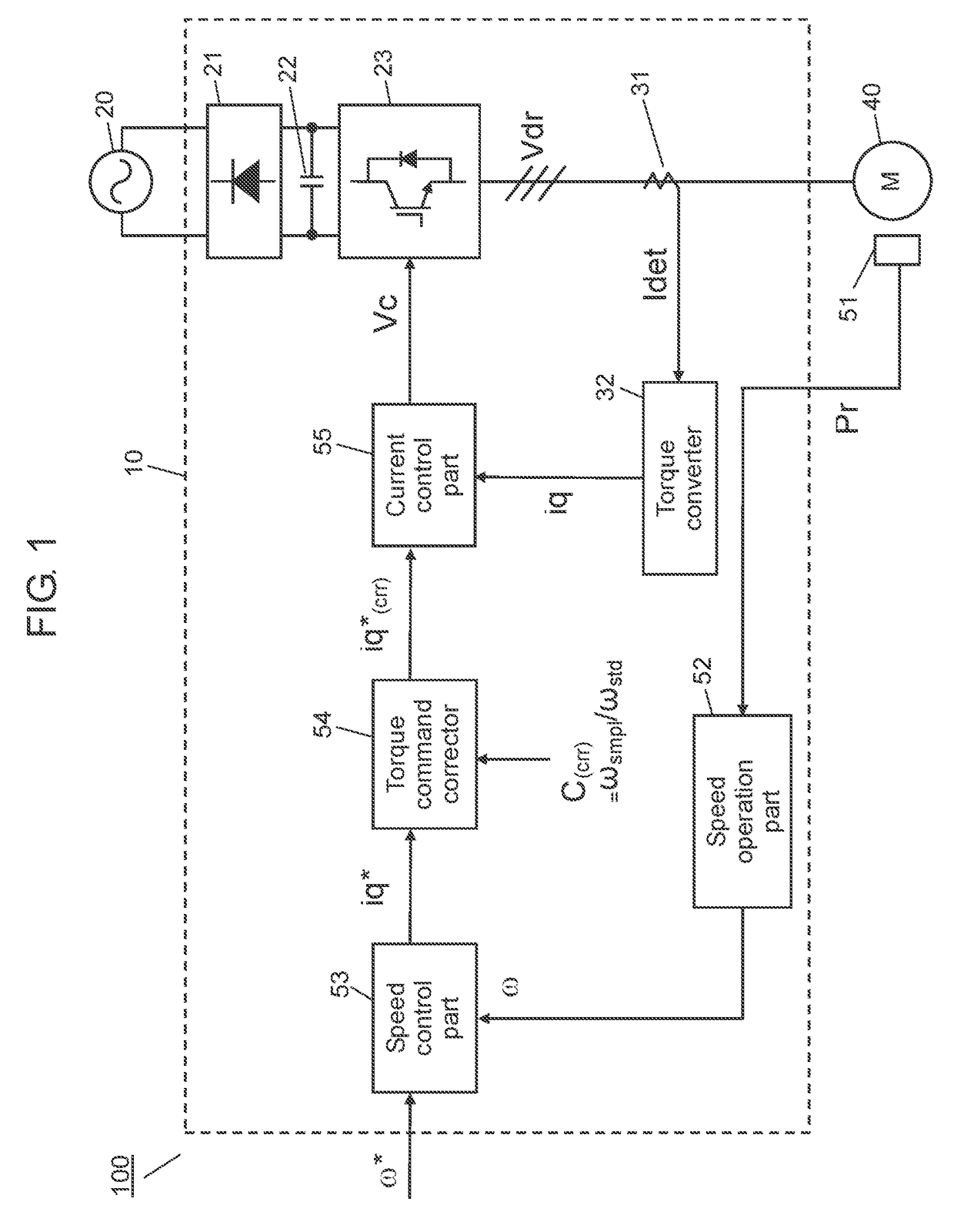
[0014]FIG. 1 is a block diagram of brushless motor 100 equipped with motor control device 10 in the first exemplary embodiment of the present invention.

[0015]As shown in. FIG. 1., brushless motor 100 in the exemplary embodiment includes motor control device 10 and synchronous motor 40. Synchronous motor 40, which is a motor in the exemplary embodiment, rotates by applying current and driving synchronous motor 40 with motor control device 10,

[0016]In motor control device 10 shown in FIG. 1., rectifying circuit 21 rectifies AC voltage from AC power source 20 to DC voltage. This is then smoothed by smoothing capacitor 22. Then, the DC voltage is supplied to three-phase inverter 23 in motor control device 10. Three-phase inverter 23 converts supplied DV voltage to required AC voltage. A drive voltage of this AC voltage is supplied to synchronous motor 40 including a permanent magnet. In this way, three-phase synchronous motor 40 having U phase, V phase, and W phase shifted by 120 degree...

second exemplary embodiment

[0044]FIG. 5 is a block diagram of brushless motor 101 equipped with motor control device 11 in the second exemplary embodiment of the present invention. Motor control device 11 includes detected torque corrector 33 for correcting detected torque iq in addition to correction of torque command iq*, compared to the first exemplary embodiment in FIG. 1. In FIG. 5, same reference marks are given to components same as those in FIG. 1, and detailed description of these components are omitted.

[0045]In FIG. 5, speed operation part 52 calculates a motor speed based on rotor position information Pr detected by position detector 51. This is sent to speed control part 53 as detected speed ω. Speed control part 53 calculates and outputs torque command iq* such that a deviation between speed command ω* and detected speed ω becomes 0.

[0046]On the other hand, torque converter 32 performs unit conversion of motor current Idet detected by current detector 31 to torque, and outputs it as detected torq...


PUM


Abstract

A motor control device at least includes a speed control part for controlling a motor rotation speed. The motor control device includes a torque correction means for suppressing variation in torque constant due to individual differences of motors. In addition, the motor control device corrects the torque constant by using a correction torque coefficient calculated based on an unloaded speed when a fixed voltage is applied. Alternatively, the torque constant is corrected using the correction torque coefficient calculated based on the motor applied voltage when the motor speed is fixed.

Description

TECHNICAL FIELD[0001]The present invention relates to motor control devices for controlling a synchronous motor and methods of calculating a correction torque coefficient in the motor control devices.BACKGROUND ART[0002]In a speed control of a synchronous motor, a conversion coefficient that expresses a relationship between a torque command and actual torque that is actually output from the motor is generally called a torque constant. In general, the torque constant is a fixed value that does not change with speed or current and configures a speed control system. However, the actual torque constant is not always fixed. The torque constant may not be fixed due to an influence of current flowing in the motor and a current control circuit.[0003]PTL1 discloses a conventional method as a technical measure to cope with it. PTL1 has a means to measure actual output torque relative to the torque command by actually driving the motor, and correct the torque command, PTL1 controls the motor u...

Claims


Application Information

Patent Timeline
Patent Type & Authority Applications(United States)
IPC IPC(8): H02P21/00H02P6/08H02P27/06
CPCH02P21/0025H02P6/08H02P27/06H02P21/00H02P23/0031H02P2205/05H02P21/20H02P6/10
Inventor SAKAMOTO, MITSUHIROYOKOUCHI, YASUYUKISONODA, DAISUKESASAKI, RYUTA
Owner PANASONIC INTELLECTUAL PROPERTY MANAGEMENT CO LTD
Why Eureka
Try Eureka