Interference cancellation circuit for a receiver

Active Publication Date: 2010-09-16
XUESHAN TECH INC
View PDF2 Cites 10 Cited by
  • Summary
  • Abstract
  • Description
  • Claims
  • Application Information

AI Technical Summary

Benefits of technology

[0013]In view of the description above, an objective of the present invention is to provide an effective and robust means of interference cancellation of an incoming signal containing a transmitted signal and at least one accompanying interferer at the frond end of a receiver for wireless communication systems.
[0014]A still another objective of the present invention is to further provide a novel complementary translational loop architecture capable of efficiently cancelling the at least one accompanying interferer around the transmitted signal with a frequency conversion scheme and a two-symmetric-paths architecture.
[0015]The present novel means of interference cancellation, with the proposed frequency conversion scheme and the two-symmetric-paths architecture, can be utilized to greatly reduce the at least one accompanying interferer around the transmitted signal and reduce the associate images at the frond end of a receiver for wireless communication systems.
[0018]To make it easier for our examiner to understand the objective of the invention, its structure, innovative features, and performance, we use a preferred embodiment together with the attached drawings for the detailed description of the invention.

Problems solved by technology

However, the noise figure will be increased due to the lowered gain of the gain-controllable LNA 101.
However, the adoption of the SAW filter 201 will occupy additional board area in the circuit, add more component cost, and cause noise figure degradation due to a SAW filter's insertion loss.
However, the phase shifts of the two paths are different due to unsymmetrical structures, so the effect of interference cancellation is limited.
Besides, a high quality RF filter is physically difficult to be implemented on-chip and the high insertion loss of the on-chip RF filter if at all will also significantly degrade the receiver sensitivity.
However, the mixer 402 and mixer 404 will produce additional images, and the phase shifts of the two paths are different due to unsymmetrical structures, so the effect of interference cancellation is limited.

Method used


Image

  • Interference cancellation circuit for a receiver
  • Interference cancellation circuit for a receiver
  • Interference cancellation circuit for a receiver

Examples


Embodiment Construction

[0028]The present invention will be described in more detail hereinafter with reference to the accompanying drawings that show the preferred embodiments of the invention.

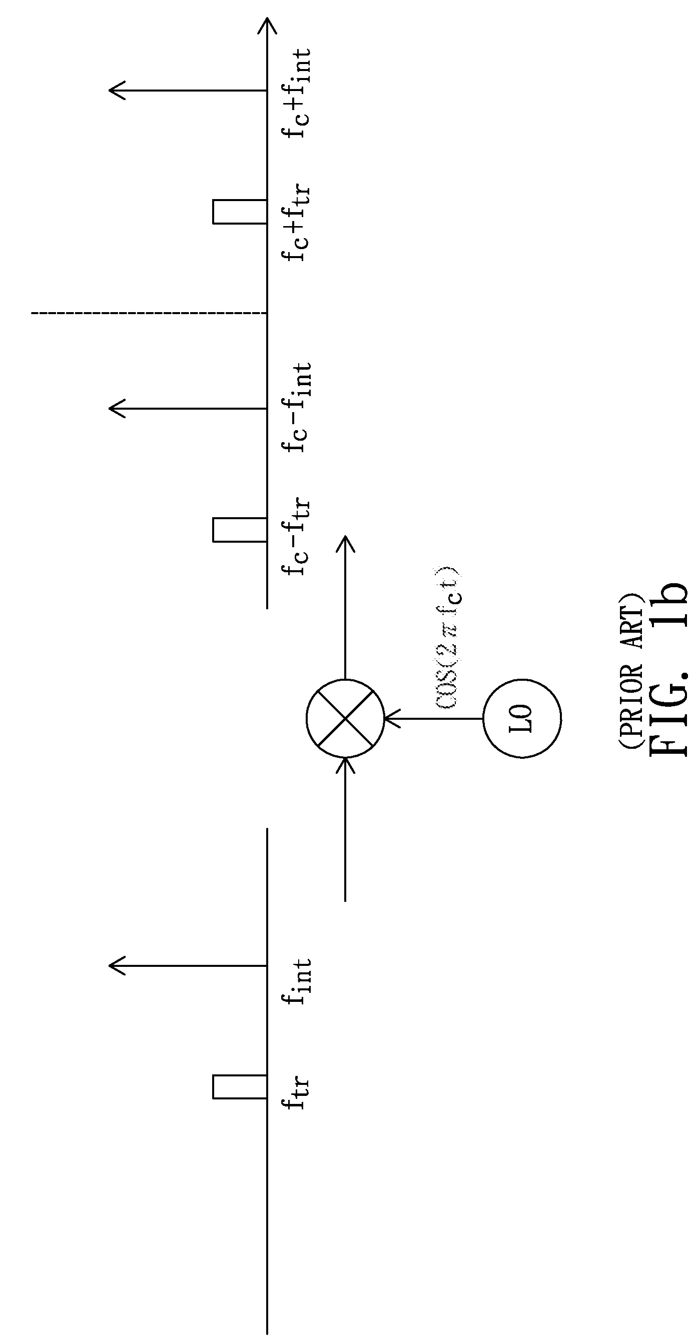
[0029]As is known in the wireless communication, the frequency conversion of a signal cos(2πfst) performed with a mixer according to a carrier signal cos(2πfct) of frequency fc can be expressed as

cos(2πfst)×cos(2πfct)=(½){cos(2π(fc+fs)t)+cos(2π(fc−fs)t)},

i.e. the signal located at fs will be converted to a signal located at fc−fs and simultaneously an image signal located at fc+fs. Now consider an incoming signal composed of a transmitted signal cos(2πftrt) located at ftr and an interferer cos(2πfintt) located at fint, the incoming signal being converted with a mixer according to a carrier signal cos(2πfct) of frequency fc. As a result, there will be four components in the converted signal located at fc−ftr, fc−fint, fc+ftr, fc+fint respectively(as shown in FIG. 1b).

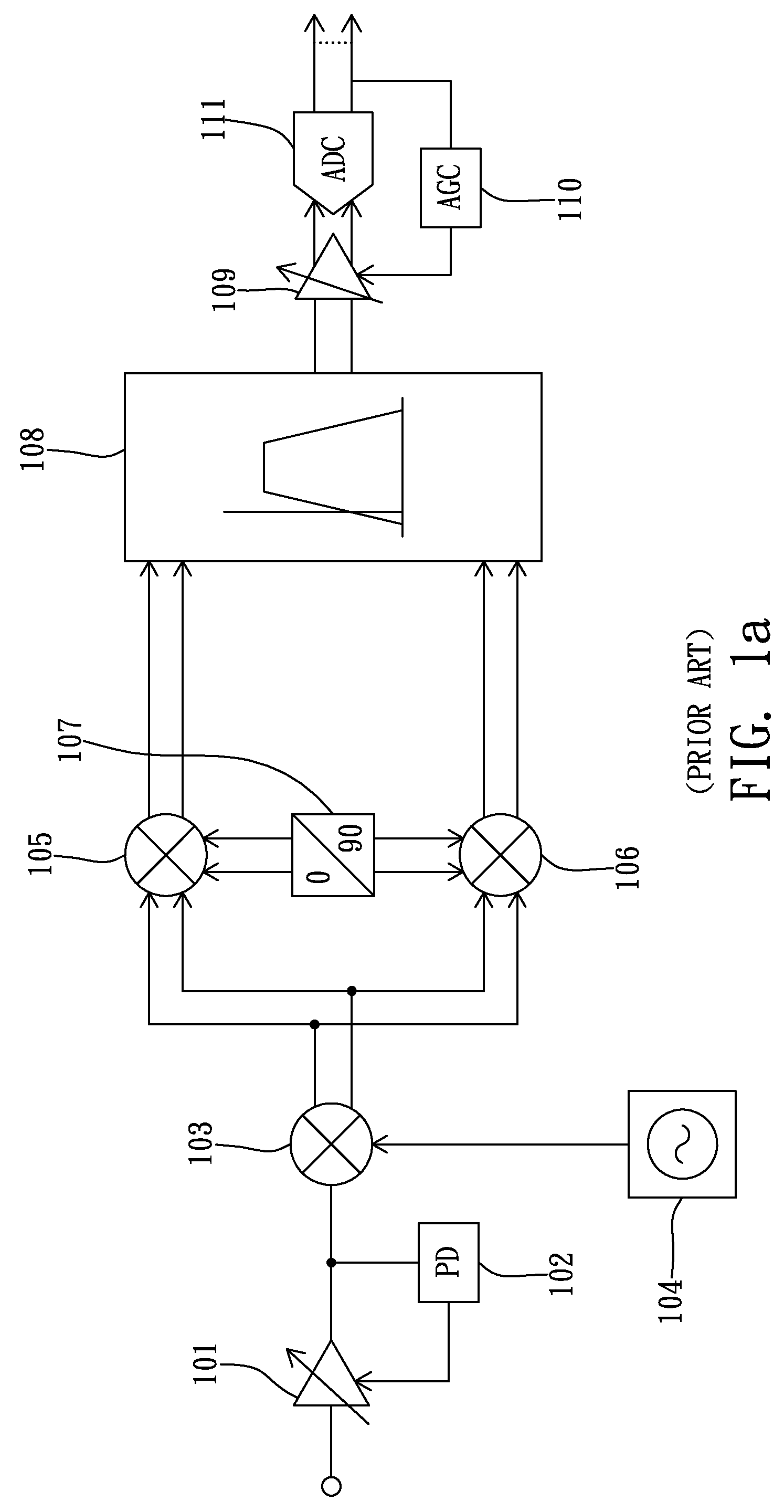
[0030]As mentioned in the description of the relat...


PUM


Abstract

The invention discloses an interference cancellation circuit for a receiver to process an input signal which is carried on a first carrier frequency and includes a transmitted signal and at least one interference signals. The interference cancellation circuit comprises a down-converter for converting the input signal to dc location to generate a down-converted signal; a first path circuit for processing the down-converted signal to generate a first processed signal which includes the transmitted signal and the interference signals; a second path circuit for processing the down-converted signal to generate a second processed signal which includes only the interference signals; and a combiner for generating an output signal by combining the first processed signal and the second processed signal.

Description

BACKGROUND OF THE INVENTION[0001]1. Field of the Invention[0002]The present invention relates to an interference cancellation circuit, and more particularly to an interference cancellation circuit capable of performing interference cancellation of an incoming signal. The incoming signal includes a transmitted signal and at least one accompanying interference signals at the frond end of a receiver for wireless communication systems. The accompanying interference signals in the incoming signal are usually stronger than the transmitted signal so it may saturate the LNA (Low Noise Amplifier) and thereby ruin the transmitted signal.[0003]2. Description of the Related Art[0004]To describe the related art of the present invention, the relation between a LNA and the other parts of a typical wireless receiver shall be introduced first. Please refer to FIG. 1a, which shows the architecture of a typical wireless receiver. As shown in FIG. 1a, the typical wireless receiver at least comprises a ...

Claims


Application Information

Patent Timeline
IPC IPC(8): H04B1/10
CPCH04B1/1036
Inventor YANG, CHAO-TUNGPAI, HUNG CHUANSUN, WEIGANG
Owner XUESHAN TECH INC
Why Eureka
Try Eureka