Interferometric photovoltaic cell

a photovoltaic cell and interferometer technology, applied in the field of optoelectronic transducers, can solve the problems of increasing the amount of light absorbed, affecting the supply of fossil fuels, and affecting the availability of fossil fuels

Inactive Publication Date: 2010-09-23
SNAPTRACK
View PDF103 Cites 47 Cited by
  • Summary
  • Abstract
  • Description
  • Claims
  • Application Information

AI Technical Summary

Benefits of technology

[0008]Certain embodiments of the invention include interferometrically tuned photovoltaic cells wherein reflection from interfaces of layered PV devices coherently sum to produce an increased electric field in an active region of the photovoltaic cell where optical energy is converted into electrical energy. Such interferometrically tuned or interferometric photovoltaic devices (iPVs) increase the absorption of optical energy in the active region of the interferometric photovoltaic cell and thereby increase the efficiency of the device. In various embodiments, one or more optical resonant cavities and / or optical resonant layers are included in the photovoltaic device to increase the electric field concentration and the absorption in the active region. The optical resonant cavities and / or layers may comprise transparent non-conducting materials, transparent conducting material, air gaps, and combinations thereof. Other embodiments are also possible.

Problems solved by technology

Fossil fuels are a non-renewable source of energy that is depleting rapidly.
The large scale industrialization of developing nations such as India and China has placed a considerable burden on the available fossil fuel.
In addition, geopolitical issues can quickly affect the supply of such fuel.
However, the use of solar energy as an economically competitive source of renewable energy is hindered by low efficiency in converting light energy into electricity.

Method used


Image

  • Interferometric photovoltaic cell
  • Interferometric photovoltaic cell
  • Interferometric photovoltaic cell

Examples


Embodiment Construction

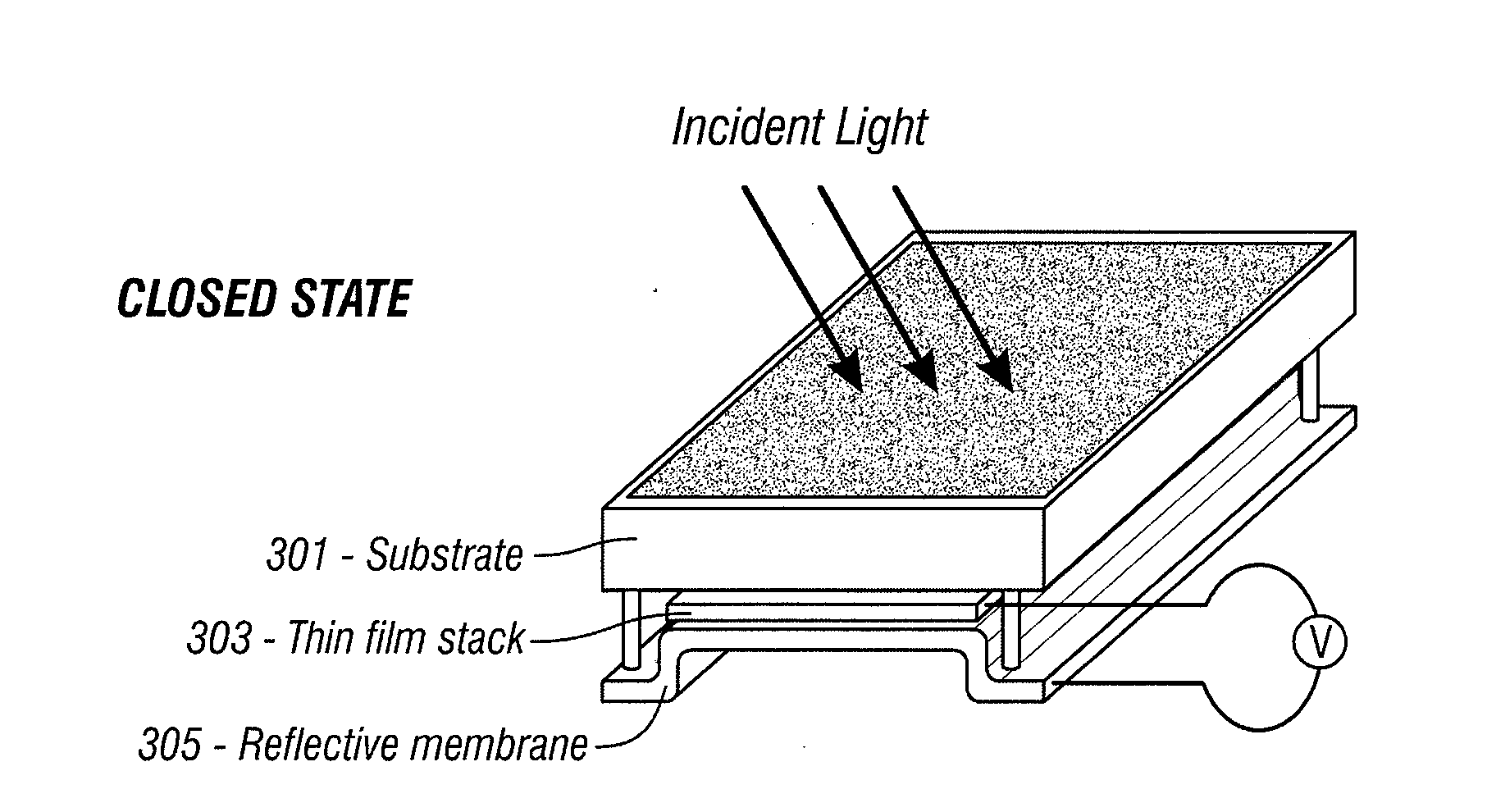
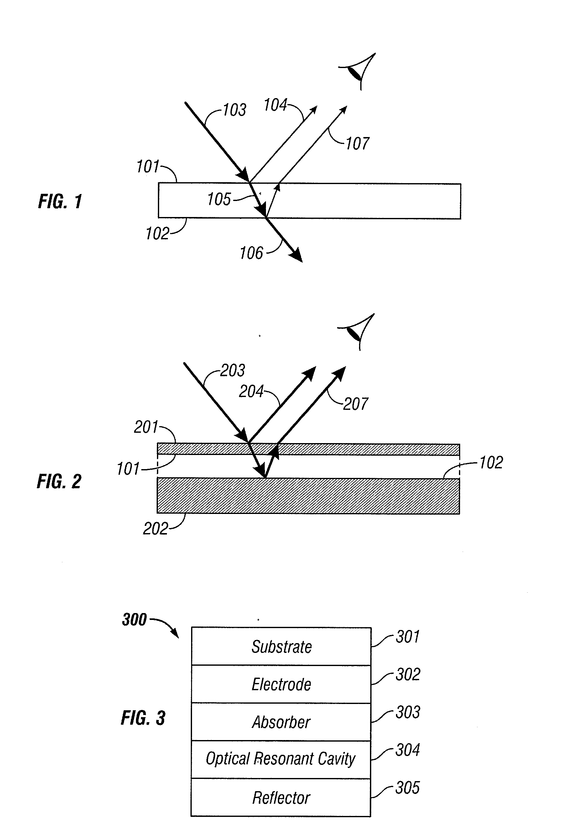
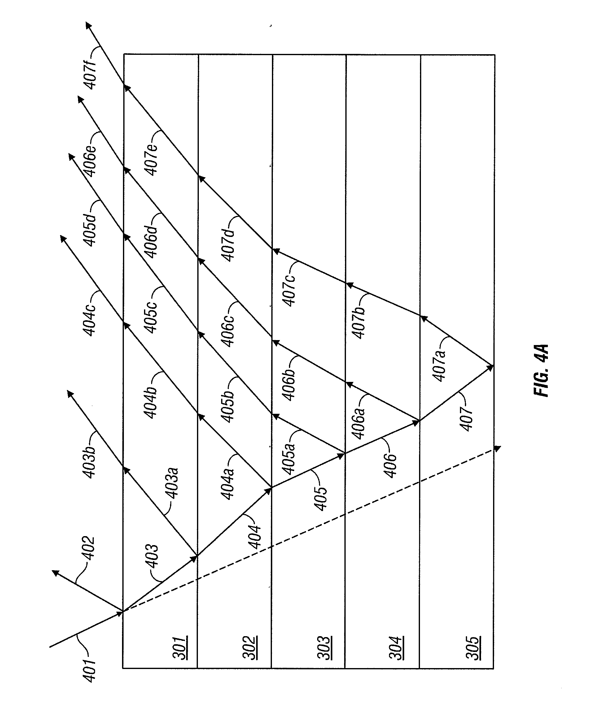
[0092]The following detailed description is directed to certain specific embodiments of the invention. However, the invention can be embodied in a multitude of different ways. In this description, reference is made to the drawings wherein like parts are designated with like numerals throughout. As will be apparent from the following description, the embodiments may be implemented in any device that comprises a photovoltaic material. MEMS devices may be coupled to photovoltaic devices as described herein below.

[0093]An optically transparent dielectric film or layer such as shown in FIG. 1 is an example of an optical resonant cavity. The dielectric film or layer may comprise a dielectric material such as glass, plastic, or any other transparent material. An example of such an optical resonant cavity is a soap film which may form bubbles and produce a spectrum of reflected colors. The optical resonant cavity shown in FIG. 1 comprises two surfaces 101 and 102. The two surfaces 101 and 1...


PUM


Abstract

Certain embodiments include interferometrically tuned photovoltaic cells wherein reflection from interfaces of layered photovoltaic devices coherently sum to produce an increased field in an active region of the photovoltaic cell where optical energy is converted into electrical energy. Such interferometrically tuned or interferometric photovoltaic devices (iPV) increase the absorption of optical energy in the active region of the interferometric photovoltaic cell and thereby increase the efficiency of the device. In various embodiments, one or more optical resonant cavities and / or optical resonant layers is included in the photovoltaic device to increase the electric field concentration and the absorption in the active region.

Description

CROSS-REFERENCE TO RELATED APPLICATIONS[0001]This application is a divisional of U.S. application Ser. No. 11 / 949,699 filed on Dec. 3, 2007, titled “INTERFEROMETRIC PHOTOVOLTAIC CELL,” (Atty. Docket No. QMRC.003A) which claims benefit under 35 U.S.C. § 119(e) to U.S. Provisional Application Ser. No. 60 / 995,259 filed on Sep. 24, 2007, titled “INTERFEROMETRIC LIGHT TRAPPING FOR PHOTOVOLTAIC CELL” (Atty. Docket No. QMRC.003PR2). Each of the above-identified application is hereby expressly incorporated herein by reference in its entirety.BACKGROUND[0002]1. Field of the Invention[0003]The present invention relates generally to the field of optoelectronic tranducers that convert optical energy into electrical energy, such as for example photovoltaic cells.[0004]2. Description of the Related Art[0005]For over a century fossil fuel such as coal, oil, and natural gas has provided the main source of energy in the United States. The need for alternative sources of energy is increasing. Fossil ...

Claims


Application Information

Patent Timeline
Patent Type & Authority Applications(United States)
IPC IPC(8): H01L31/00
CPCG02B5/284H01L31/02165H01L31/02167H01L31/0232H01L31/0322H01L31/056H01L31/0527Y02E10/52Y02E10/541H01L31/18H01L31/0336H01L31/02325Y02E10/548Y02P70/50
Inventor KHAZENI, KASRAKOTHARI, MANISHXU, GANG
Owner SNAPTRACK
Why Eureka
Try Eureka