Cleat Spike Insole

a technology of cleats and insoles, applied in the field of sports shoes, can solve the problems of reducing the performance of running shoes, limiting reducing the use of cleats, so as to reduce the manufacturing cost, facilitate the manufacturing process, and ensure the effect of comfor

Inactive Publication Date: 2011-10-20
JENNINGS JAMES EDWARD
View PDF0 Cites 30 Cited by
  • Summary
  • Abstract
  • Description
  • Claims
  • Application Information

AI Technical Summary

Benefits of technology

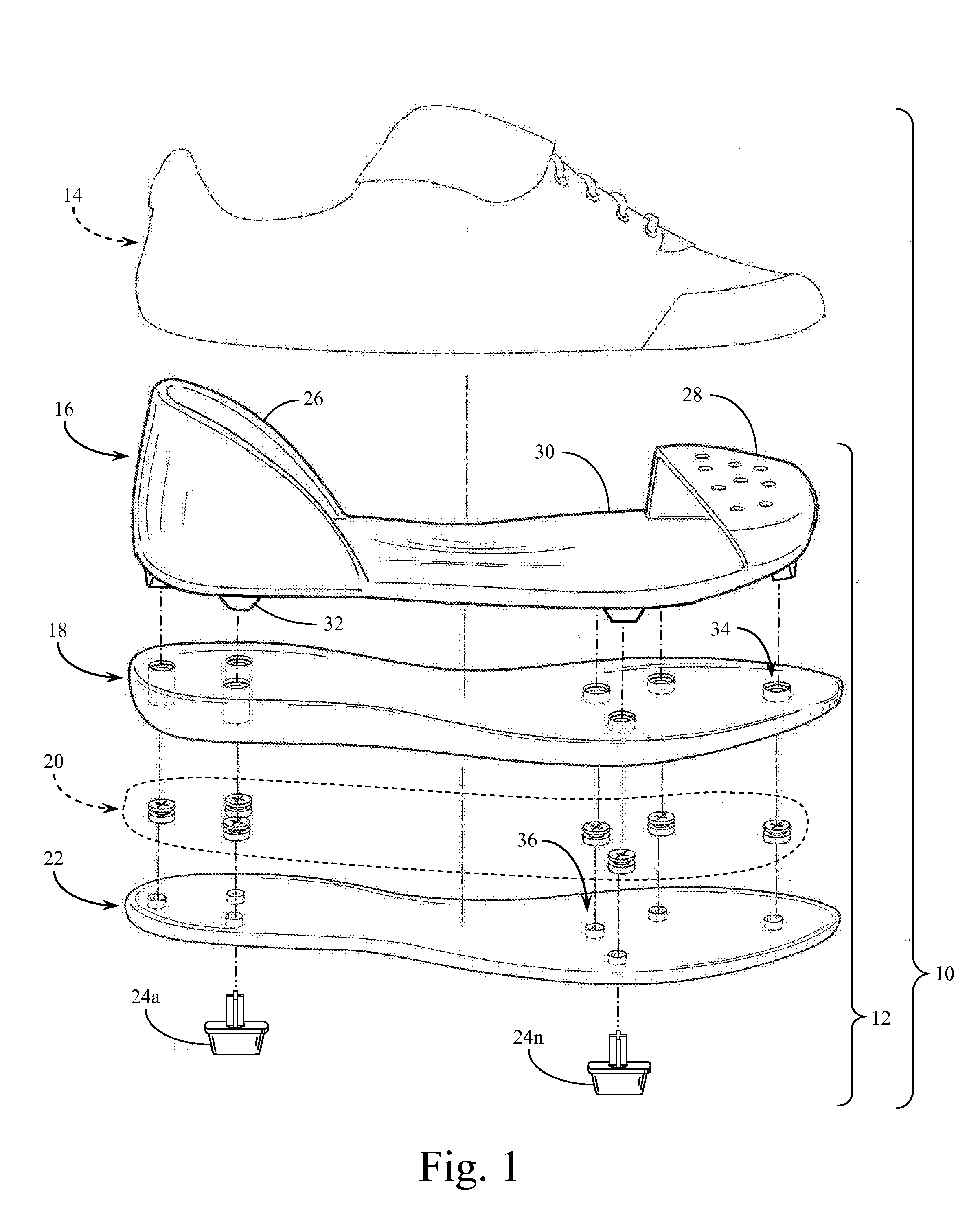
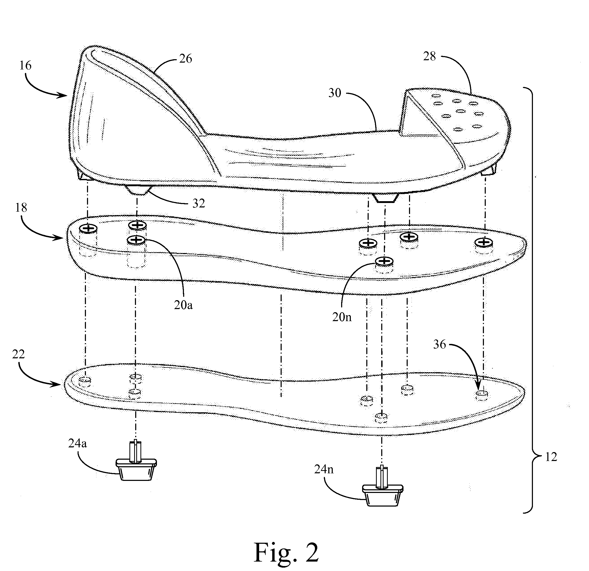
[0014]The CSI unit fills the inner space adjacent to the topside surface of the sole. The insole cradle unit includes a sock lined plastic layer encompassing a heel cup, arch support and toe protector having cleats / spikes attached, affixed or receptacle means for said cleats / spikes. The sock liner comprises a compressibly resilient foam layer having top and bottom surfaces sized and shaped for insertion into the footwear and for supporting the foot. The sole (mid / out) attenuates reaction forces and absorbs energy as the footwear contacts the surface. The midsole forms the middle layer of the cushion sole and may be composed of resilient foam material, such as polyurethane, or similar or combination of materials. The cleats / spikes are provided at the bottom of the sole for ground engaged traction. The CSI shoe structure reduces manufacturing cost and simplifies manufacturing processes.
[0015]The sock liner is a very soft foam insert that adds plenty of comfort and relieves cleat / spike pressure with light cushioning and shock absorption of the shoe. The foam lower layer has compressibility sufficient to permit the layer to resiliently compress under the foot in response to pressure applied by the foot during periods of a gait cycle when the footwear impacts the ground thereby absorbing shock and cushioning the foot during impact. The sock liner may further comprise an open cell layer. The bottom surface of the upper layer is permanently bonded to the top surface of the lower layer for spacing the lower layer from the foot to reduce heat transfer from the lower layer to the foot and insulate. The sock liner may include a closed cell lower layer and a porous upper level permitting air to pass through to cool and dry the foot. The sock lined bonded plastic unit may be removable and replaceable. The CSI shoe improves stability, propulsion, sides-to-sides and gains maximum foot control. The cleat / spike insole has direct contact creating a natural synergy with the athlete's foot.
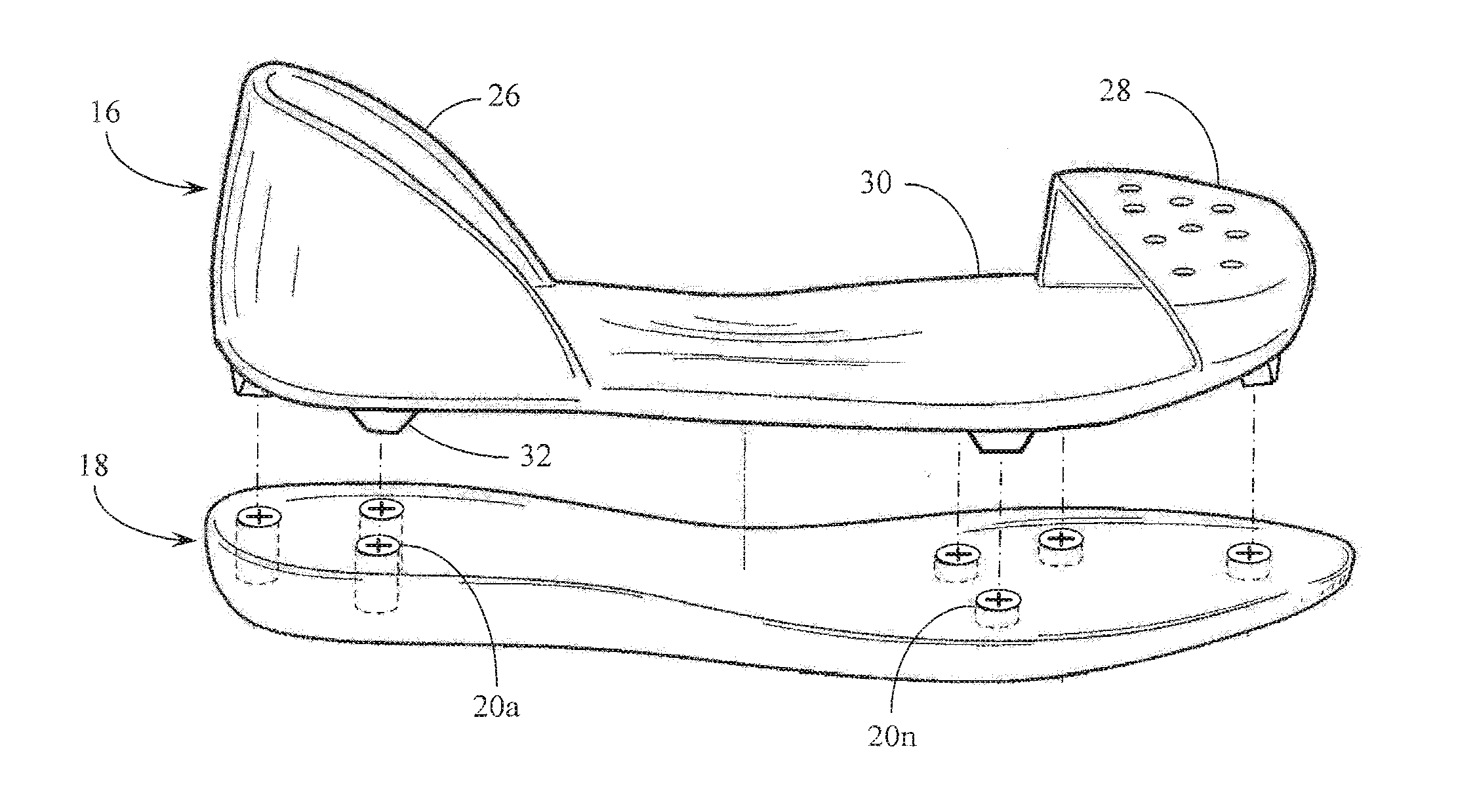
[0016]The plastic cradle insole of the present invention provides support and is used for cleats / spikes attachment. The plastic insole cradle can be formed by injection molding a resin into a desired shape, including a receptacle. The receptacle is sized and dimensioned to receive a threaded or locking system head of the shank (cleat component). The resin can be enhanced having a fibrous composition of nylon or glass. Arch support is placed beneath the medial region, and considerable weight may be saved, as conventional mid / out sole materials may be reduced or eliminated. The resistance to flex is important in the arch support region during the gait cycle. In addition, the anterior of the support requires an increase of flexibility for toeing off.
[0017]Cleated athletic shoes typically include a sole having an upper extending upwardly from the sole and into which the foot of the athlete is positioned and secured in place. A conventional cleated athletic shoe usually includes a pattern of cleats in the rearfoot portion and in the forefoot portion of the outsole. CSI spikes / cleats attach to the plastic insole with a screw, threaded shank head, shank lock system and / or have a receptacle disposed on the exterior surface in the molding process. An engagement receptacle would have threads on the interior surface wall. Shoes with studs are designed for efficient, reliable attachment and disengagement. This allows the player to use the optimal stud for different field conditions.
[0018]The sole of a typical athletic shoe accounts for 70% of the total shoe weight. Thus, to significantly reduce the total weight of a shoe, steps must be taken to reduce the weight of the sole. To achieve a sole which is lightweight, the components thereof must be structured from a elimination concept to materials which are functionally efficient. The unisole structure of the present invention is lightweight, provides flexibility, rigidness and is easier to assemble than conventional midsole and outsoles. The unisole is attached to the upper by lasting and / or adhesives. In addition, the unisole reduces molding costs due to the fact that the midsole / outsole, or sole can be formed with one mold from a combined midsole / outsole material which eliminates the need for a separate outsole mold. By using one mold as compared to two molds, simultaneously reduces the thickness, cost and weight. As mentioned above, the unisole uses a combined midsole / outsole material to reduce the weight and increase the stability of the shoe. The stability is vital due to cleat pressure. The unisole and alternative components are molded from a compound comprising cushioning foam (for example, polyurethane or ethyl vinyl acetate) and an abrasion resistant rubber. The EVA foam and compounds are available from Eclipse Polymers Co. Ltd. EVA or polyurethane are both capable of producing a suitable sole, however the primary requirements of the present invention are durability and stiffness value. The unisole is made by injection or form molding. The bottom surface may be molded with a plurality of tread elements to increase the traction. A tread element texturing may take the form of v-shaped flex groves, waffles, or other dimensional projections.

Problems solved by technology

The design of athletic shoes has become a science, but there has been little advancement for cleated footwear.
Outsole plates severally limit running performance.
In particular, outsole plates can cause discomfort, fatigue, and injury.

Method used


Image

  • Cleat Spike Insole
  • Cleat Spike Insole
  • Cleat Spike Insole

Examples


Embodiment Construction

[0032]Reference is made first to FIG. 1 for an overall description of an exploded assembly view of the components that make up the improved cleat / spike insole shoe foundation of the present invention. FIG. 1 represents what may be a typical shoe construction including all of the components for a completed shoe. The assembly 10 of shoe components is shown with the components in their general orientation prior to or in the process of assembly. The present invention generally comprises the shoe foundation 12 components which include all components except for the shoe upper 14 which is shown in dashed outline form in FIG. 1. The balance of the components are shown with alignment lines generally positioned to indicate the point of attachment for cleat / spikes 24a-24n, two of which are shown in FIG. 1 as representative of the total number that might be provided on the shoe.

[0033]The first primary component of the present invention is detachable insert cradle 16 which is a molded plastic co...


PUM


Abstract

A shoe foundation assembly for receiving and retaining a number of cleats or spikes into the bottom sole of the shoe such as might be utilized in various sporting events. The shoe foundation assembly includes a unitarily molded shoe cradle component with a toe guard at a first end, a heel guard at a second end, and arch medial. An outsole is bonded to the midsole component sized and shaped to be positioned on the underside base of the shoe cradle component. The detachable cradle incorporates hillock apertures for positioning a number of sealable inserts to receive the cleat/spikes. Bonded to the midsole is an outsole component having a plurality of slit apertures also positioned to receive the plurality of cleat/spikes. A number of different types of cleats or shoe spikes may be inserted into the apertures in the outsole and through the sealable inserts within the midsole. Each of the cleat/spikes incorporates a structure for the retention of the cleat/spike onto the shoe foundation.

Description

CROSS REFERENCE TO RELATED APPLICATIONS[0001]This is a Continuation-in-Part of application Ser. No. 11 / 526,372, filed Sep. 25, 2006, which is a Continuation of application Ser. No. 10 / 900,217, filed Jul. 27, 2004, now abandoned.BACKGROUND OF THE INVENTION[0002]1. Field of the Invention[0003]The specialization of sports shoes, i.e. football, soccer, baseball, and basketball, has drawn the invention of a multiple or two way sport shoe. This specialization has resulted in the relocation of hardened plastic materials into the interior as cradle insole support and as a means for cleat / spike attachment. The present invention retains a comfortable soft sole versus a conventional hard outsole plate.[0004]2. Background of the Invention[0005]The modern cleated athletic shoe is a combination of many elements which have specific functions, all of which work together for support and protection during an athletic event. The design of athletic shoes has become a science, but there has been little ...

Claims


Application Information

Patent Timeline
Patent Type & Authority Applications(United States)
IPC IPC(8): A43B13/18A43C15/00
CPCA43B5/02A43C15/161A43B17/02A43B13/30
Inventor JENNINGS, JAMES EDWARD
Owner JENNINGS JAMES EDWARD
Why Eureka
Try Eureka