

Structural assembly for vehicles
a structure and vehicle technology, applied in the field of vehicles, can solve the problems of limited energy absorption capacity, limited rail length, and restricted rail size, and achieve the effects of improving impact performance, reducing load capacity, and reducing length
- Summary
- Abstract
- Description
- Claims
- Application Information
AI Technical Summary
Benefits of technology
Problems solved by technology
Method used
Image

Examples
Embodiment Construction
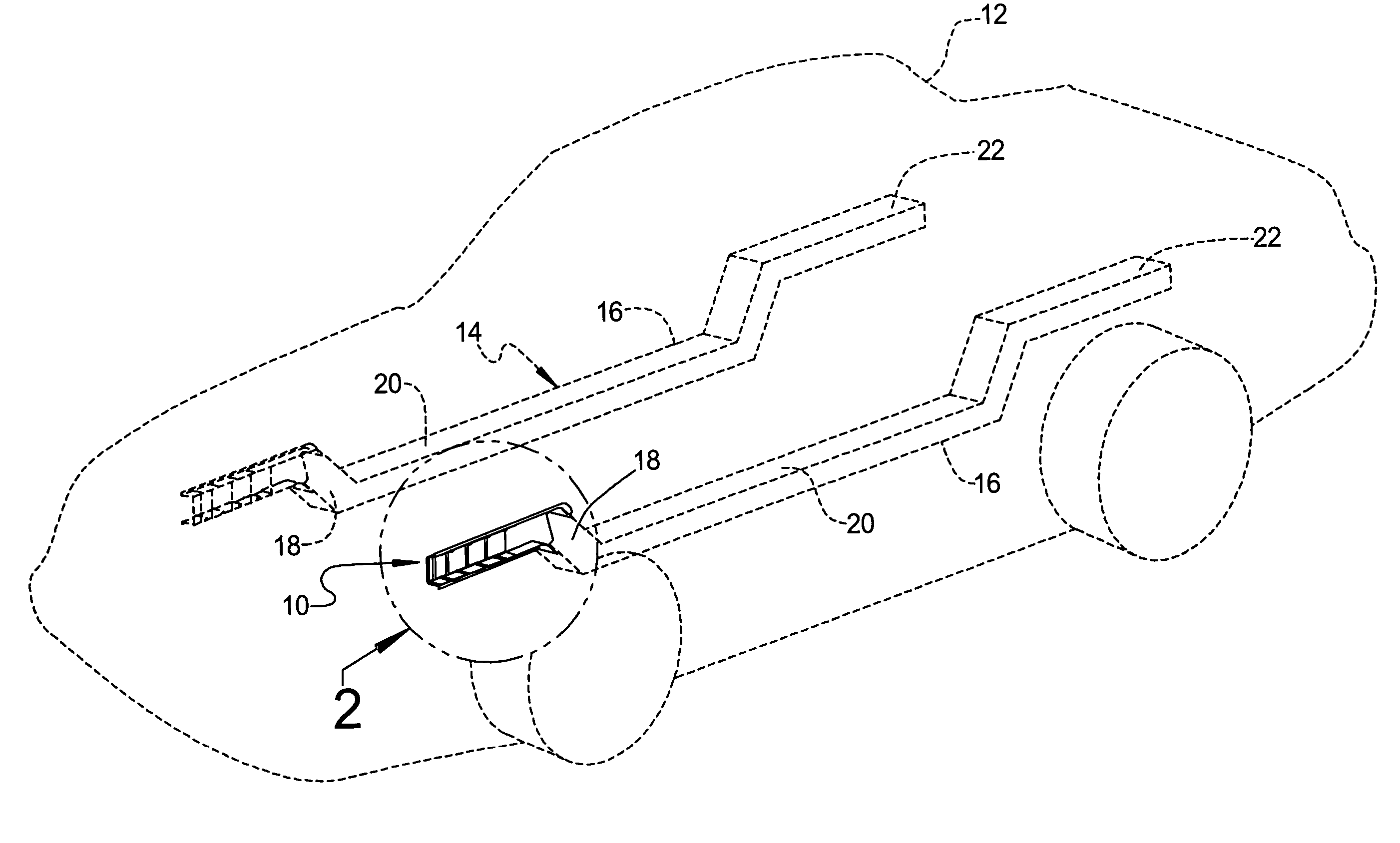
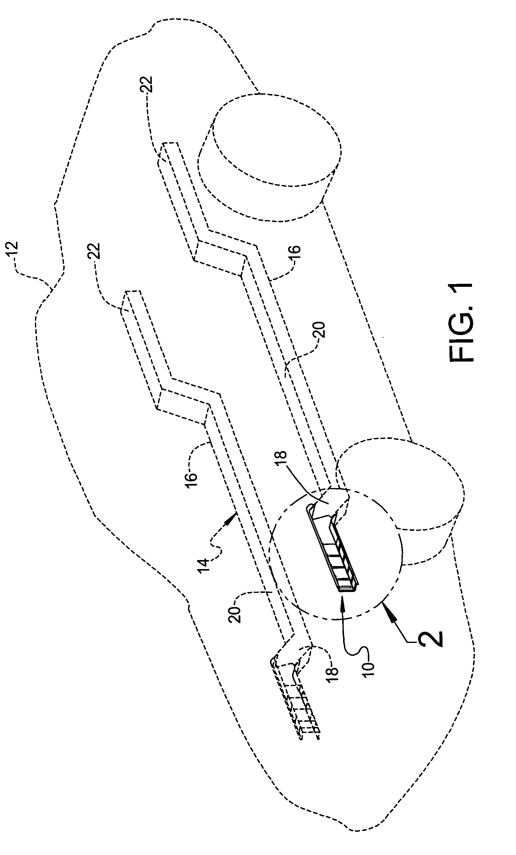
[0016] Referring to the drawings and in particular FIG. 1, one embodiment of a structural assembly 10, according to the present invention, is generally shown for a vehicle 12. The vehicle 10 includes a vehicle frame, generally indicated at 14. The vehicle frame 14 has at least one, preferably a pair of rails 16. The rails 16 are spaced laterally in parallel relationship with respect to each other and extend longitudinally forwardly and rearwardly, respectively. Each of the rails 16 has a forward portion 18, a central portion 20, and a rear portion 22. In one embodiment, the forward portion 18 includes the structural assembly 10. It should be appreciated that, in another embodiment, the rear portion 22 may also include the structural assembly 10. It should also be appreciated that, except for the structural assembly 10, the vehicle 12 is conventional and known in the art.
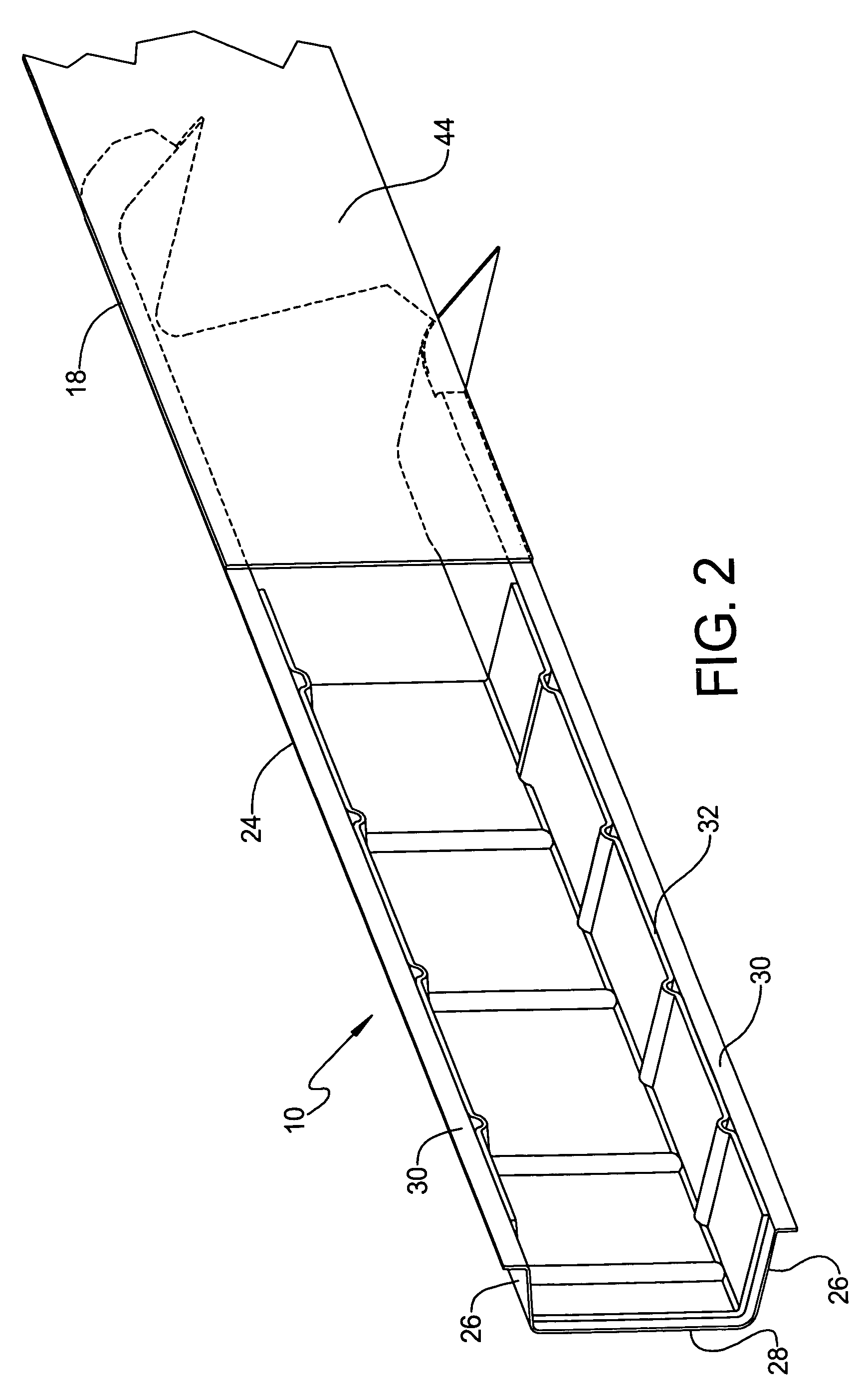
[0017] Referring to FIGS. 1 through 5, the structural assembly 10 includes a structural member such as, for examp...
PUM
 Abstract
Description
Claims
Application Information