Vehicle body rear structure

a rear structure and rear body technology, applied in the direction of roofs, transportation and packaging, vehicle arrangements, etc., can solve the problems of difficult effective dispersion of input load, and achieve the effect of increasing the aerodynamic performance of the vehicle and reducing the risk of collision

Inactive Publication Date: 2008-10-16
HONDA MOTOR CO LTD
View PDF3 Cites 31 Cited by
  • Summary
  • Abstract
  • Description
  • Claims
  • Application Information

AI Technical Summary

Benefits of technology

[0019]In the vehicle body rear structure, when the load is input along the front-rear direction of the stiffening panel, the stiffening panel efficiently transmits the load to the framework member via the middle floor cross member. As a result, a transmission of the load via the rear frames, which are offset above the stiffening panel, is reduced in the vehicle body rear structure. That is, since a transmission efficiency of the load upon a rear-end collision is increased by the stiffening panel, an excellent collision energy absorption can be achieved in the vehicle body rear structure.
[0020]Therefore, a collision safety performance of the vehicle body rear structure upon a rear-end collision can be increased. In addition, in the vehicle body rear structure, since the stiffening panel covers the lower side of the fuel tank, both the upper and lower sides of the fuel tank can be protected.
[0021]In addition, in the vehicle body rear structure, since the stiffening panel reduces irregularities on the bottom side of the vehicle body, an aerodynamic performance of the vehicle provided with the vehicle body rear structure can be increased in running.
[0026]In the vehicle body rear structure according to the present invention, both the collision safety performance upon a rear-end collision and aerodynamic performance of the vehicle can be increased concurrently.

Problems solved by technology

As a result, in the conventional vehicle body rear structure described above, it has been difficult to effectively disperse the input load into the receiving bracket 110, tension-compression bars 101, and side sills 105 via the tension-compression bars 101.

Method used


Image

  • Vehicle body rear structure
  • Vehicle body rear structure
  • Vehicle body rear structure

Examples


first embodiment

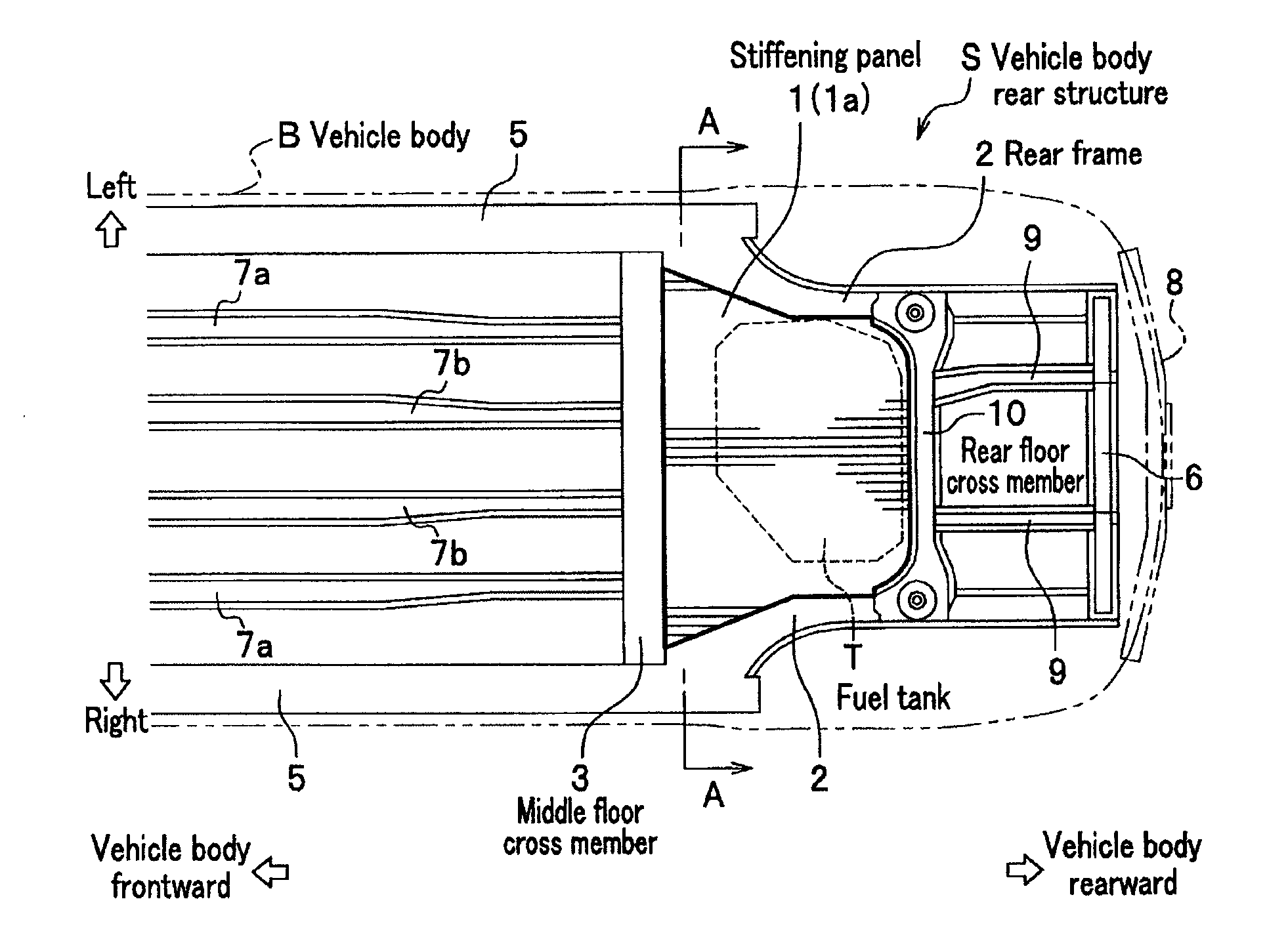
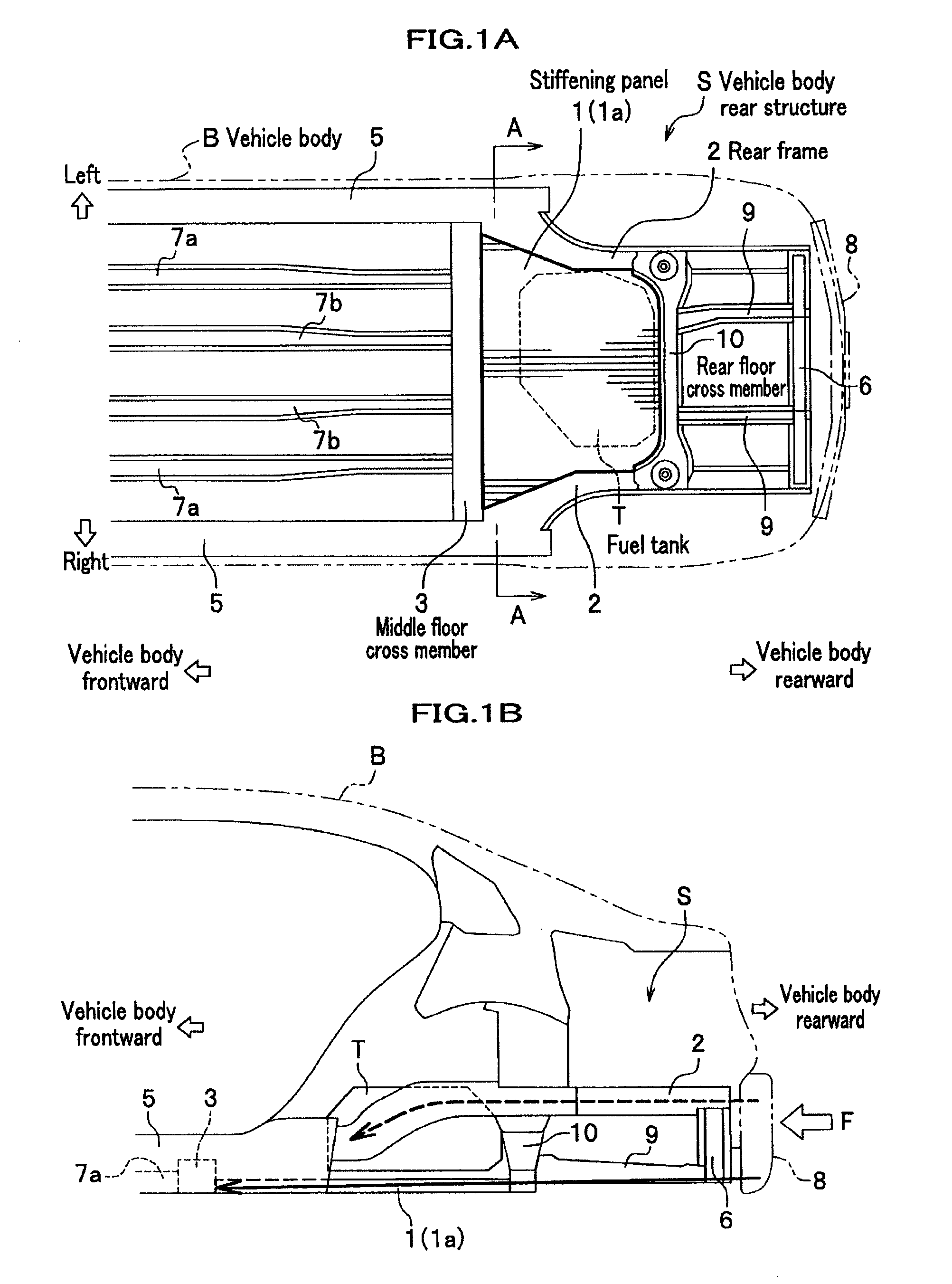
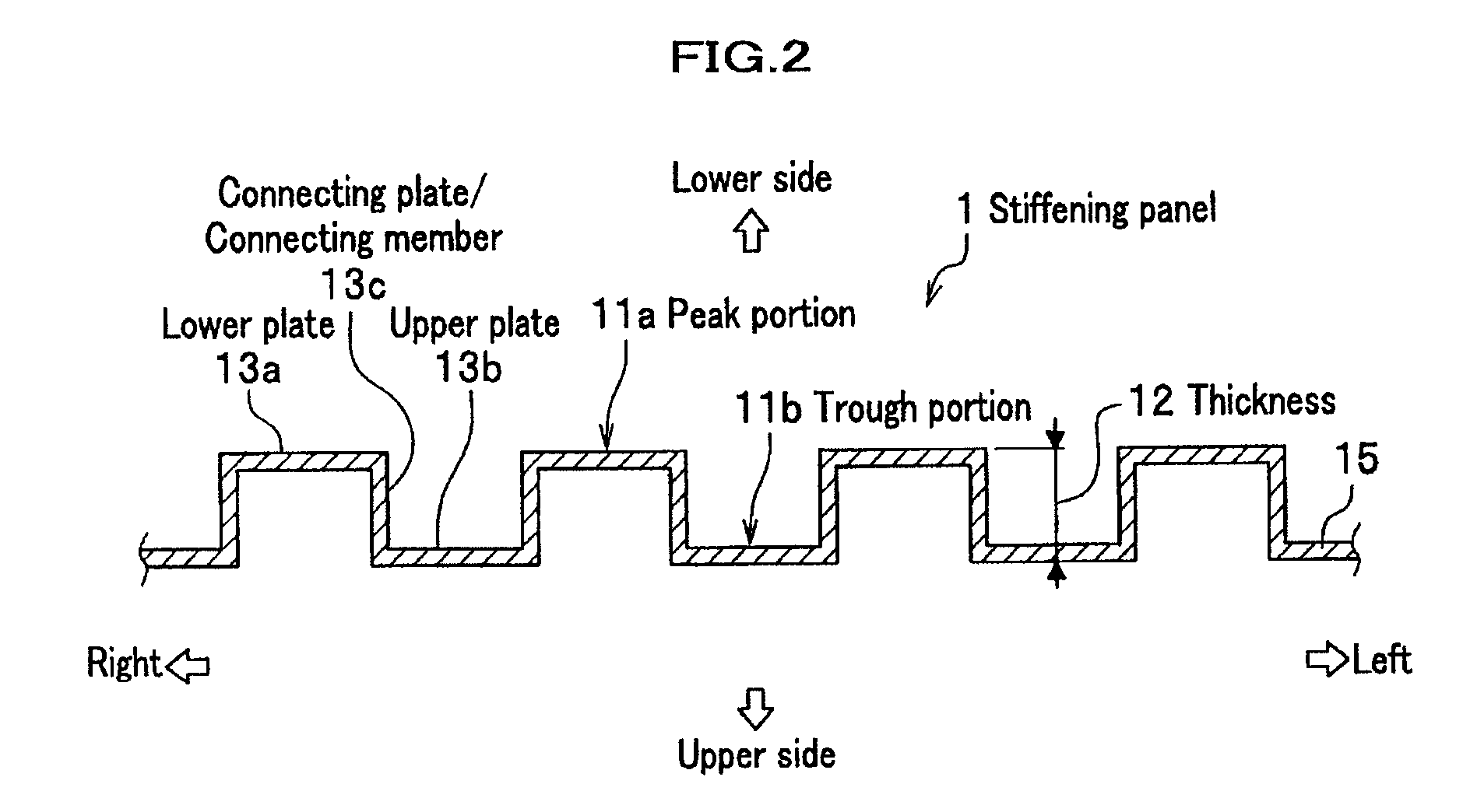
[0035]Next, a vehicle body rear structure according to a first embodiment of the present invention will be explained in detail by referring to drawings as needed. FIG. 1A is a bottom plane view schematically showing a vehicle body structure including a vehicle body rear structure according to the first embodiment. FIG. 1B is a side view schematically showing the vehicle body rear structure according to the first embodiment. FIG. 2 is a partial cross sectional view partially showing a stiffening panel taken along an A-A cross section in FIG. 1A. FIG. 3A to FIG. 3C are cross sectional views showing modified samples of a stiffening panel to be used for a vehicle body rear structure according to the first embodiment. It is noted that in the explanations hereinafter, directions of left, right, top and bottom are based on the left, right, top and bottom of a vehicle (automobile) which is normally on the ground.

[0036]As shown in FIG. 1A, a vehicle body rear structure S according to the emb...

second embodiment

[0062]Next, a vehicle body rear structure according to a second embodiment of the present embodiment will be explained by referring to drawings as needed. In the second embodiment, only a stiffening panel structure used for the vehicle body rear structure is different from that of the first embodiment. Therefore, explanations will be made mainly on the stiffening panel used for the second embodiment. FIG. 4A to FIG. 4D are cross sectional views of the stiffening panels used for the vehicle body rear structure according to the second embodiment. It is noted that FIG. 4A to FIG. 4D correspond to cross sections of the stiffening panel taken along an A-A line in FIG. 1A.

[0063]As shown in FIG. 4A, a stiffening panel 1a to be used for the embodiment is composed of a core member 16a and an upper panel 17b and lower panel 17a which sandwich the core member 16a, and has a so-called sandwich structure. The core member 16a connects the upper panel 17b and lower panel 17a. It is noted that the ...


PUM


Abstract

A vehicle body rear structure, which includes: rear frames disposed on both side of a rear portion of a vehicle; a rear floor cross member bridged between the rear frames and jointed to each of the rear frames; a middle floor cross member which is disposed ahead of the rear floor cross member to extend in a vehicle width direction; and a stiffening panel covering a lower side of a fuel tank which is disposed in a space surrounded by the each of the rear frames, the rear floor cross member, and the middle floor cross member, wherein the stiffening panel comprises an upper plate, a lower plate, and a connecting member which connects the upper plate and the lower plate; and wherein the stiffening panel has a thickness which transmits a load upon a rear-end collision to a framework member ahead of the stiffening panel.

Description

CROSS REFERENCE TO RELATED APPLICATIONS[0001]This application claims the foreign priority benefit under Title 35, United States Code, §119(a)-(d) of Japanese Patent Application No. 2007-010064, filed on Jan. 19, 2007, the contents of which are hereby incorporated by reference.BACKGROUND OF THE INVENTION[0002]1. Field of the Invention[0003]The present invention relates to a vehicle body rear structure.[0004]2. Description of Related Art[0005]Conventionally, a vehicle body rear structure which is provided with approximately a Y-shaped stiffening structure in plane view has been known. This is disclosed in, for example, U.S. Pat. No. 6,834,910. FIG. 6 is a bottom plane view schematically showing a conventional vehicle body rear structure as seen from a bottom side of a vehicle body.[0006]As shown in FIG. 6, the stiffening structure is formed in approximately a Y-shape by a support member 109 and a pair of tension-compression bars 101 (tank lower frames). The support member 109 is dispo...

Claims


Application Information

Patent Timeline
Patent Type & Authority Applications(United States)
IPC IPC(8): B62D25/08
CPCB62D21/152B62D25/087B62D25/2027
Inventor YAMAGUCHI, TOSHIZUMIKAWABE, SATORUTSUYUZAKI, TAKUMI
Owner HONDA MOTOR CO LTD
Why Eureka
Try Eureka