High vacuum heat insulation low temperature liquefied gas storage tank

A low-temperature liquefied gas and high-vacuum technology, which is applied in the direction of gas processing/storage, gas/liquid distribution and storage, fixed-capacity gas storage tanks, etc. question

Active Publication Date: 2005-10-19
CHINA INTERNATIONAL MARINE CONTAINERS (GROUP) CO LTD +1
View PDF3 Cites 27 Cited by
  • Summary
  • Abstract
  • Description
  • Claims
  • Application Information

AI Technical Summary

Problems solved by technology

Among the existing technologies, the upper and inner support structures of low-temperature storage tanks currently used at home and abroad include: 1) The heat-insulating pad structure between the inner tank and the outer shell, but it cannot effectively solve the problem of large heat leakage from the support due to the small distance between high-vacuum multi-layer heat insulation 2) The stainless steel casing structure between the inner and outer heads is difficult to manufacture, the distance between the inner and oute

Method used


Image

  • High vacuum heat insulation low temperature liquefied gas storage tank
  • High vacuum heat insulation low temperature liquefied gas storage tank

Examples


Embodiment Construction

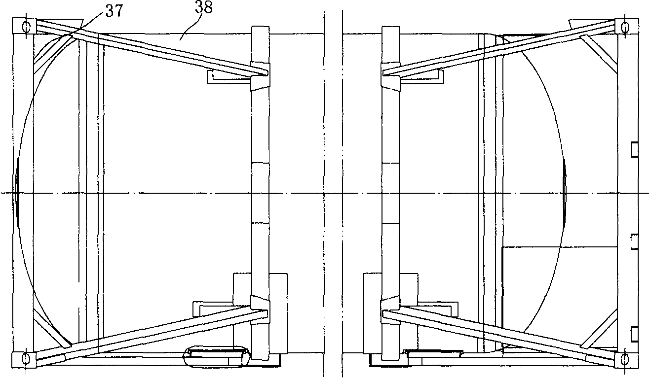
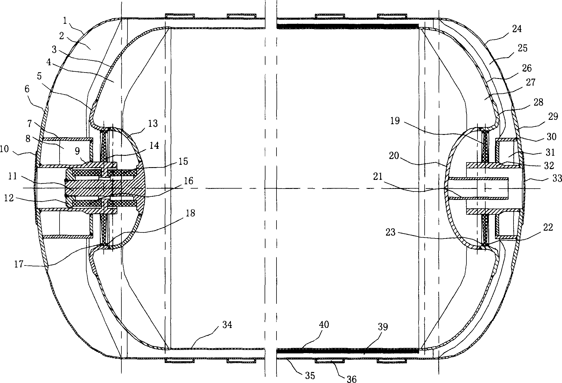
[0025] The specific implementation of the present invention will be further described below in conjunction with the accompanying drawings. Such as figure 1 As shown, the present invention comprises a frame 37 and a tank body 38 welded together in an appropriate manner. Such as figure 2 As shown, the tank body includes the left shell head 1, the left shell head reinforcement plate 2, the inner tank left head head 3, the inner tank left head reinforcement plate 4, the left transition tube 5, the left reinforcement plate 6, and the left reinforcement plate Cylinder 7, left reinforcing plate 8, left support tube 9, left sealing plate 10, stainless steel shaft 11, lock nut 12, left reversed small head 13, left radial support plate 14, second spacer 15, the first A spacer 16, left radial support disk left fixed ring 17, left radial support disk right fixed ring 18, right radial support disk 19, right reversed small head 20, process tube 21, right radial support disk right Fixed ...


PUM


Abstract

The high vacuum heat insulating low temperature liquefied gas storing tank includes frame and tank body. The tank body consists of outer casing, inner container and combined support structures connecting the outer casing and the inner container. The combined support structures are set between the inner sealing head and outer sealing head on two ends of the tank to bear the radial load and the axial load with great bearing force. The heat conducting area between the inner container and the outer casing is small, and the inner container has great effective loading volume.

Description

technical field [0001] The present invention relates to a low-temperature liquefied gas storage and transportation equipment, and more specifically relates to a high-vacuum heat-insulated low-temperature liquefied gas storage tank, which may be a tank truck or a tank container suitable for efficiently transporting low-temperature liquefied gas. The present invention realizes that the impact force and the temperature change of the carrier medium that the low-temperature liquefied gas storage and transportation equipment bears during the operation process meet the requirements of the low-temperature liquefied gas The requirements for storage and transportation, and the vacuum layer between the inner tank and the outer cylinder of the cryogenic container is the thinnest, and finally the loading rate of the cryogenic liquefied gas is maximized. The invention belongs to cryogenic engineering and cryogenic engineering [0002] technology field. Background technique [0003] The ...

Claims


Application Information

Patent Timeline
IPC IPC(8): B65D88/00B65D88/12F17C1/12F17C3/08F17C13/08
CPCF17C2209/232B65D88/128F17C2203/012F17C2203/0341F17C2203/015F17C2203/0629F17C2221/033F17C2201/0104F17C2205/0107F17C2223/033F17C3/08F17C2203/0636F17C2205/0126F17C2223/0161F17C13/083F17C2203/014F17C2201/054F17C2270/0171F17C2260/033F17C2203/0391F17C2201/035F17C2209/221
Inventor 汪荣顺孙洪利罗永欣石玉美
Owner CHINA INTERNATIONAL MARINE CONTAINERS (GROUP) CO LTD
Why Eureka
Try Eureka