Omnidirectional wheel and method for the assembly thereof

a technology of omnidirectional wheels and wheels, which is applied in the directions of multi-purpose tools, manufacturing tools, transportation and packaging, etc., can solve the problems of complicated installation of such wheels and problems with the bearing of all rollers

Active Publication Date: 2010-10-28
KUKA ROBOTER
View PDF13 Cites 18 Cited by
  • Summary
  • Abstract
  • Description
  • Claims
  • Application Information

AI Technical Summary

Benefits of technology

[0008]An additional object of the invention is to achieve an omnidirectional wheel while retaining opposing wheel discs, which omnidirectional wheel can be produced and operated with high bearing precision of the roller bodies.
[0033]In one embodiment of the receptacle modules, the opposing facing sides of every single roller body can respectively be associated with an angle support, wherein a pivot bearing is respectively fashioned between roller body and angle support and the angle support is attached to the receptacle module. The receptacle module must be able to enclose the roller body in a C-shape so that every roller body can be borne from its opposing facing sides so that it can rotate on the receptacle module. The receptacle module can inasmuch be manufactured in one piece, for example be cast or be cut from a solid. However, in terms of manufacturing it can also be reasonable to design the receptacle module in multiple parts. For example, in this case the receptacle modules can consist of a flat, planar base support on which are attached two opposing angle supports in order to achieve the C-shaped design of the receptacle module. This has the advantage that the bearing points to accommodate pivot bearing elements (for example ball or roller bearings) can be produced in a simple manner (in terms of manufacturing) in the angle supports before they are attached to the base supports. For example, the angle supports can be connected (for example via bolts) with the base support. Due to the detachment capability of the bolt connections, individual bearings or, respectively, angle supports can also be exchanged (for example due to wear).

Problems solved by technology

This has the disadvantage that all bearing positions must be matched to one another in terms of production so that all roller bodies are positioned concentrically and symmetrical to one another without position deviations.
As a result the installation of such wheels is complicated since the precise positions of the roller bodies must be adjusted repeatedly and laboriously during the installation.
This leads to problems with the bearing of all rollers.

Method used


Image

  • Omnidirectional wheel and method for the assembly thereof
  • Omnidirectional wheel and method for the assembly thereof
  • Omnidirectional wheel and method for the assembly thereof

Examples


Embodiment Construction

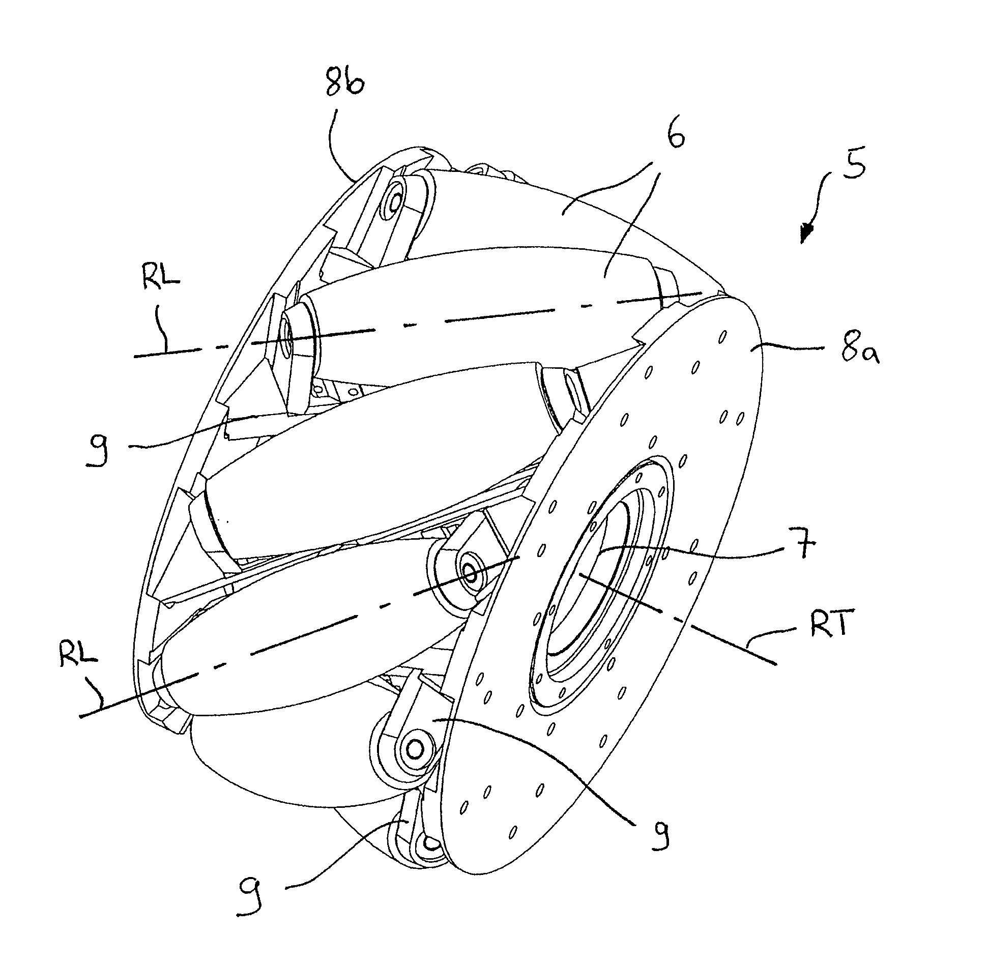
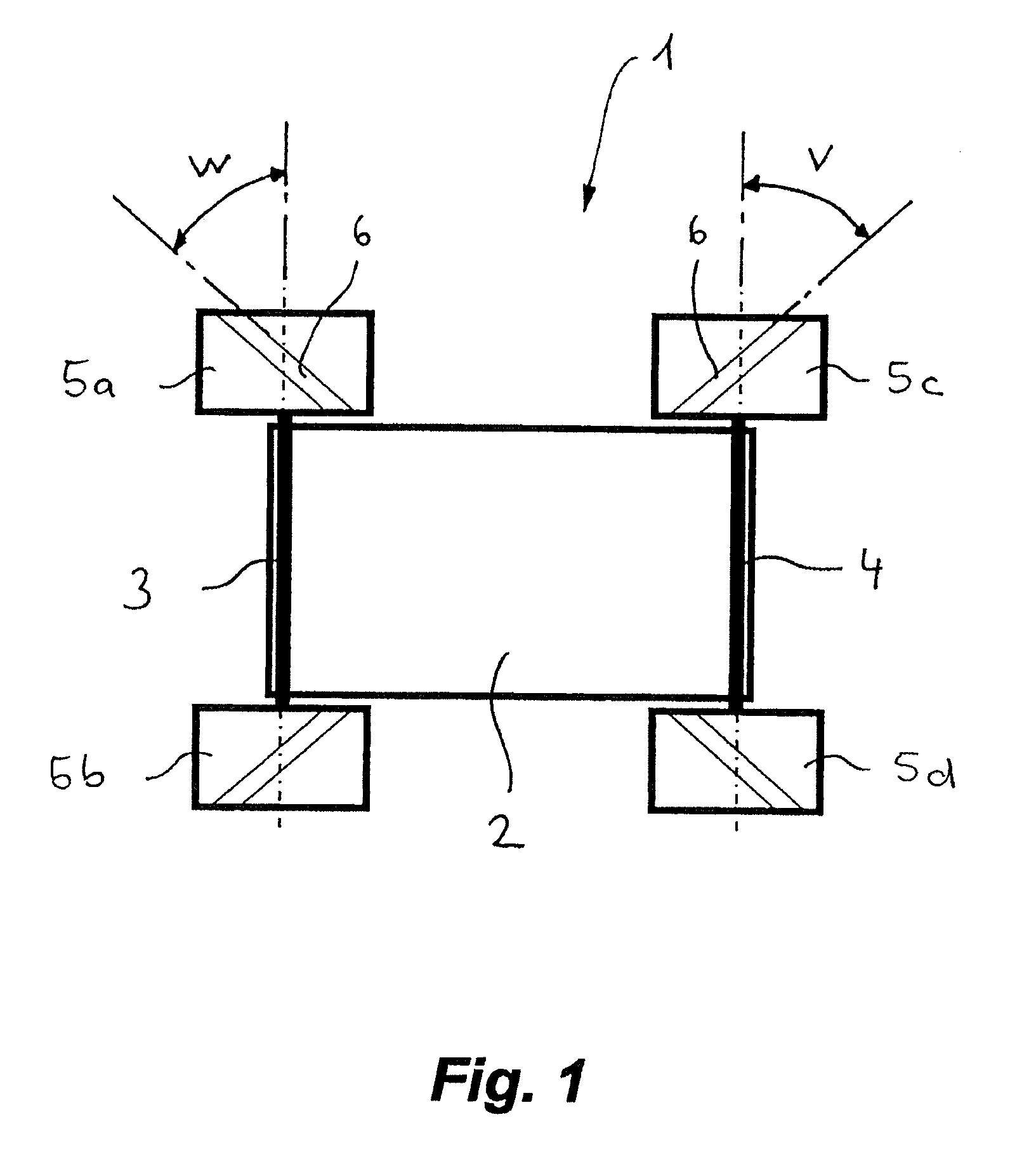
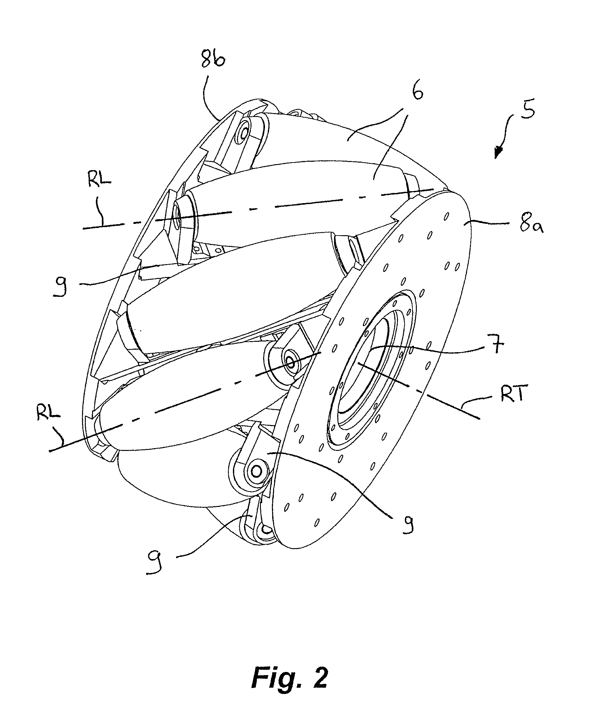
[0052]FIG. 1 shows an omnidirectionally movable carriage 1 with a chassis 2 as well as a first geometric wheel axis 3 and a second geometric wheel axis 4. Aligned along the first wheel axis 3, the chassis 2 bears a right front omnidirectional wheel 5a and a left front omnidirectional wheel 5b. Aligned along the second wheel axis 4, the chassis 2 bears a right rear omnidirectional wheel 5c and a left rear omnidirectional wheel 5d. Each omnidirectional wheel 5a, 5b, 5c, 5d is connected with its own drive. Every drive can be controlled independent of the other drives, both with regard to rotation speed and with regard to rotation direction. Each diagonal wheel pair 5a, 5c and 5b, 5d has roller bodies 6 that are aligned running in the same direction at an angle W inclined relative to the wheel axis 3 or wheel axis 4. The respective other diagonal wheel pair 5a, 5c and 5b, 5d has roller bodies 6 that are aligned running in the same direction at an angle V opposite the angle W, inclined r...


PUM

PropertyMeasurementUnit
angleaaaaaaaaaa
anglesaaaaaaaaaa
anglesaaaaaaaaaa

Abstract

An omnidirectional wheel has a hub that is rotatable around a rotational axis, and two wheel discs connected to the hub and spaced coaxially on the hub. A number of roller bodies are located between the wheel discs, evenly distributed around a circumferential edge of the wheel. The respective roller axes of the roller bodies are aligned at a diagonal angle relative to the rotational axis, and are each supported in a freely rotating manner between the wheel discs at opposite ends thereof. Each roller body is mounted in a freely rotating manner in respective modules respectively attached to the wheel discs.

Description

BACKGROUND OF THE INVENTION[0001]1. Field of the Invention[0002]The invention concerns an omnidirectional wheel and a method for installing roller bodies of an omnidirectional wheel, as well as an omnidirectional movable chassis embodying such an omnidirectional wheel.[0003]2. Description of the Prior Art[0004]The prototypical of an omnidirectional wheel is known from DE-OS 21 58 019. Such wheels can be used to move vehicles in any desired direction without having to be borne in a pivoting fashion on the vehicle. Two forward and two rear rotating drive arrangements can thereby be provided that respectively possesses an omnidirectional wheel. The drives are individually controllable and the rollers contacting the floor are arranged at an angle, wherein a first diagonal pair of wheels respectively runs at an angle in the same direction and a second diagonal pair of wheels runs inclined at a right angle to the first diagonal pair.[0005]In WO 2007 / 016917 A2 an omnidirectional wheel is d...

Claims


Application Information

Patent Timeline
Patent Type & Authority Applications(United States)
IPC IPC(8): B60B19/12B23P11/00
CPCB60B19/003B60B19/125B60B2310/202B60B2310/226Y10T16/184B60B2380/12B60B2380/14Y10T29/49826B60B2310/305
Inventor BRUDNIOK, SVEN
Owner KUKA ROBOTER
Why Eureka
Try Eureka