

Touch screen element
a touch screen element and touch screen technology, applied in the direction of electronic switching, pulse technique, instruments, etc., can solve the problems of reducing transparency, adding considerable expense, and affecting the effect of sensitivity
- Summary
- Abstract
- Description
- Claims
- Application Information
AI Technical Summary
Benefits of technology
Problems solved by technology
Method used
Image

Examples
first embodiment
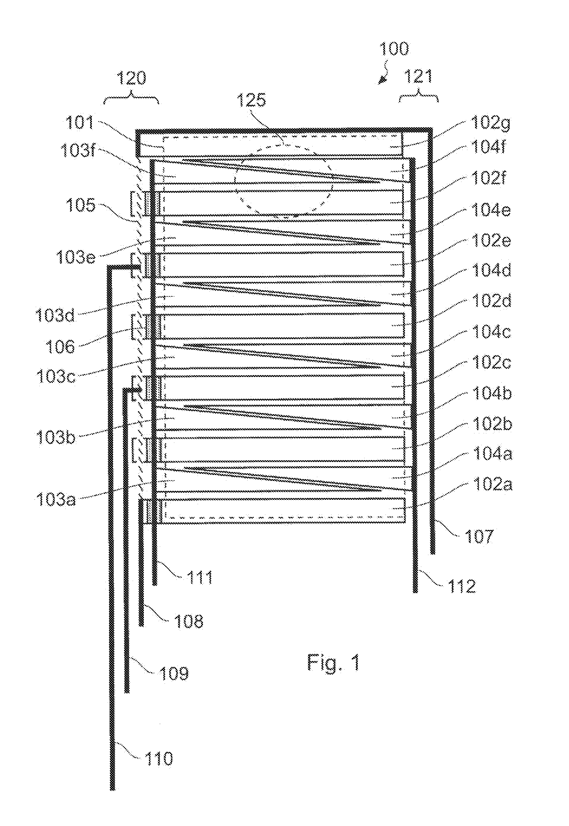
[0050]Referring to the drawings, in FIG. 1 there is shown the invention. FIG. 1 shows in plan view a capacitive touch sensing array 100 having a usable touch area 101 (shown as a dotted outline). Electrodes 102a-g resolve a first axis (shown as y), while electrodes 103a-f and 104a-f resolve a second axis (shown as x). In practice the configuration is reversible with respect to x and y in some applications. The x axis is resolved by the field gradients produced by the triangular shapes as is known in the art. Left-side and right-side connections 111 and 112 respectively are wired to a circuit (not shown) which senses the capacitive loading on these electrodes and obtains a ratiometric measurement of touch location along the x axis.
[0051]The y axis is resolved by the use of a resistive element 105 which runs along one side of the electrodes and which connects to electrodes 102a-g. The field gradient on this axis is produced by 105 in a manner known according to my co-pending U.S. appl...
second embodiment
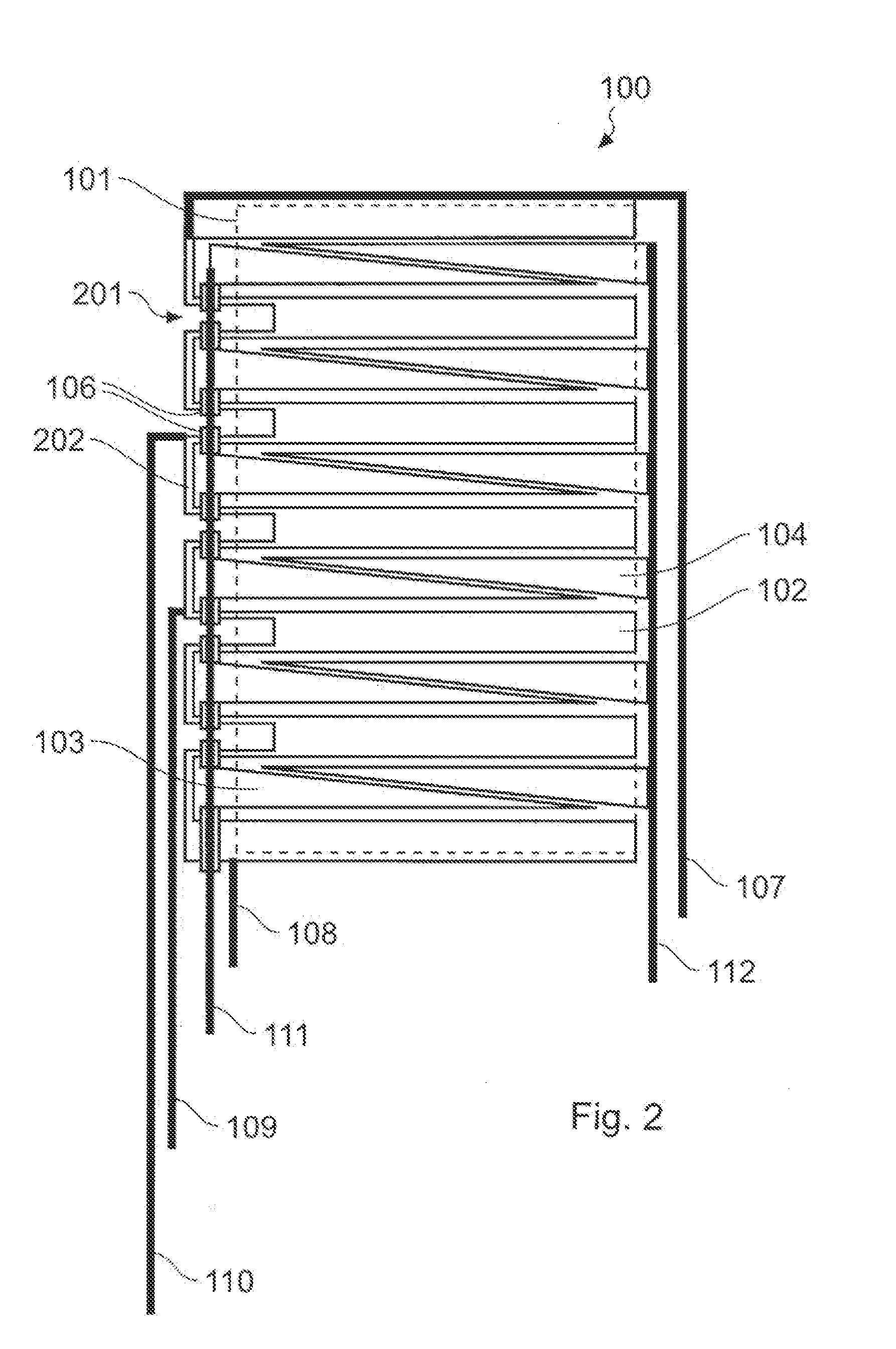
[0057]Turning now to FIG. 2, there is shown a second embodiment with a slightly different configuration of the electrode array 100. In this configuration, the resistive strip 105 is replaced by the same conductive material as used in the electrodes. In the case of ITO, a common value of sheet resistance is 300 ohms per square. In order to use the ITO itself as a resistive element, to achieve the relatively high values of end-to-end resistance required, the path length must be increased in some manner. In FIG. 2 this is achieved by using the bars 102 as an additional path for the current to flow, by means of cutouts 201 within the bars. Bar-to-bar traces 202 are also made of the electrode material so that the entire structure composed of electrodes 102, 103, 104 and traces 202 are made in one step on the same layer. Dielectric 106 separates the electrode conductor from the left x connection 111 to prevent short circuits.
third embodiment
[0058]Turning now to FIG. 3, there is shown a third embodiment with yet another configuration of electrode array 100, whereby the required resistive strip shown as 105 in FIG. 1 is incorporated into the y resolving bars 102 themselves. The path for the resistance is serpentine from top to bottom (as shown) with resistive routing 202 connecting each bar to the next. The end bars 310, 311 at the top and bottom of the electrode pattern do not participate in the resistive path; as a result they are equipotential with respect to their connecting wires 107 and 108. Since the right x connection 112 still needs to connect to the right triangles 104, additional thin crossover dielectric 301 is required between each of ones 104 and 112.
[0059]Dotted outlines 320 and 325 show the areas of finger contact and hand shadow respectively which will be discussed further below.
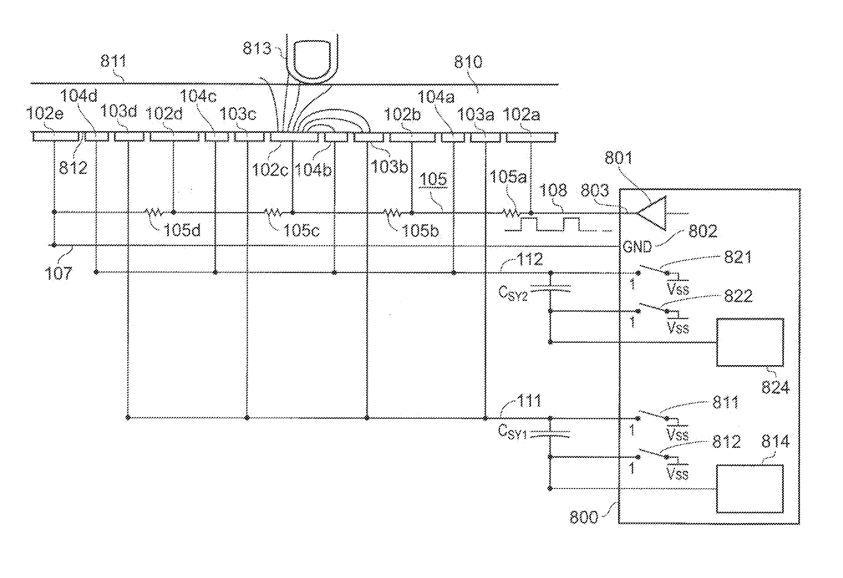
[0060]FIG. 4 shows an ACE capable circuit 400 for operating the touch screen electrode set 100. As shown, there are six sensing...
PUM
 Abstract
Description
Claims
Application Information