

Universal Stands for Portable Electronic Devices
a technology for electronic devices and universal stands, which is applied in the field of universal stands for portable electronic devices, can solve the problems of not having a standard shape for portable electronic devices of a particular category (or subcategory of goods), and many more types of portable electronic devices have yet to be developed
- Summary
- Abstract
- Description
- Claims
- Application Information
AI Technical Summary
Benefits of technology
Problems solved by technology
Method used
Image

Examples
first embodiment
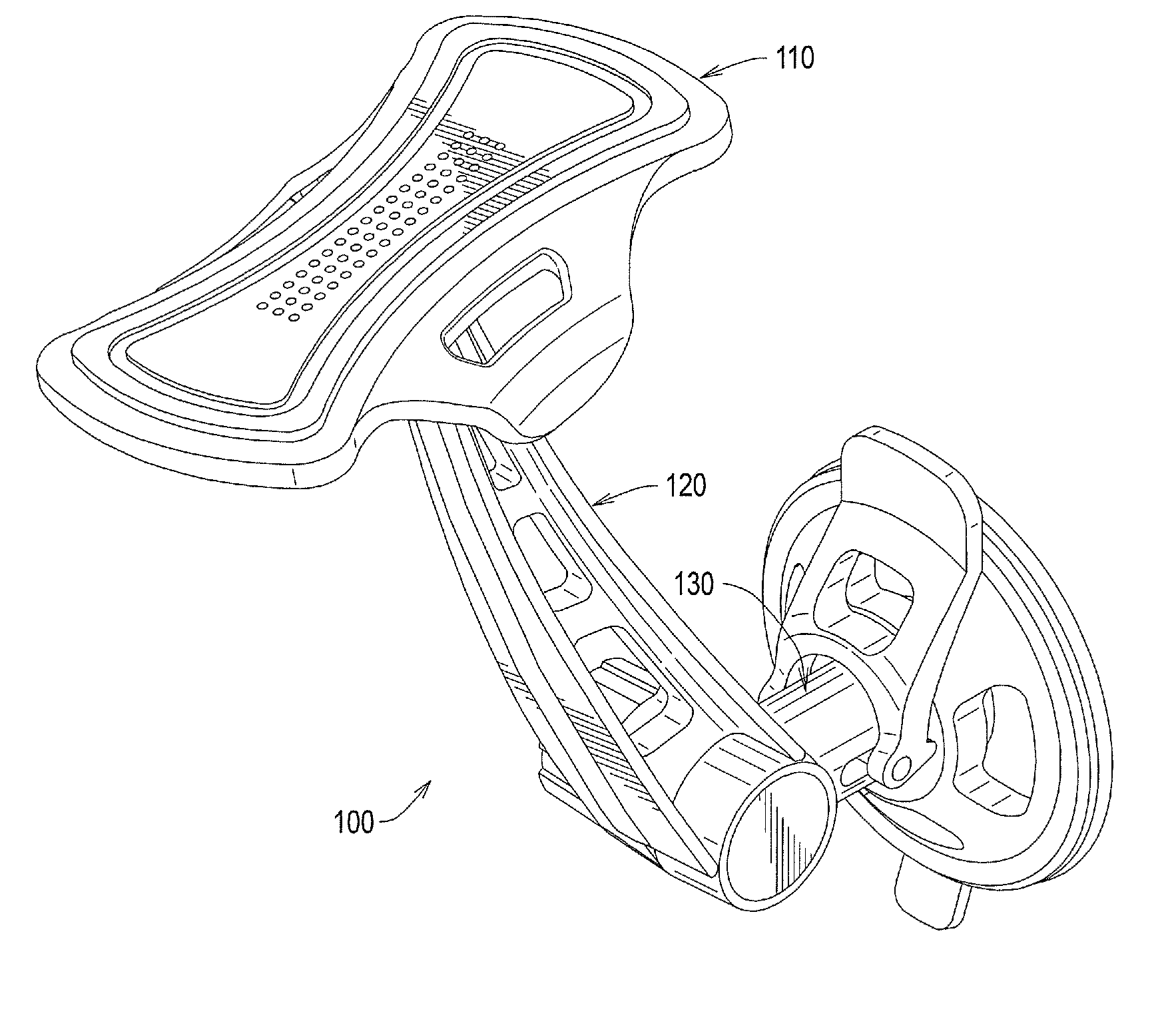
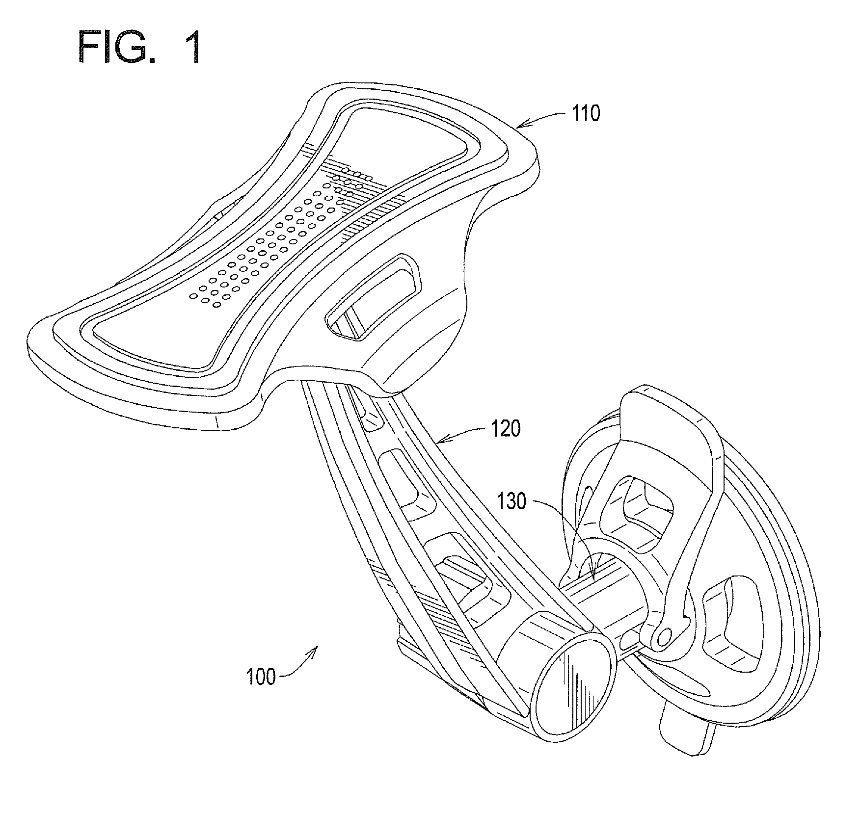
[0099]a stand 100 for a portable electronic device is illustrated in FIG. 1. The stand 100 includes a display platform 110, an arm 120 and a base 130.
[0100]It should be understood that FIG. 1 illustrates one embodiment of an exemplary stand and that, in other embodiments, one or more of the display platform 110, arm 120 or base 130 may be eliminated. Furthermore, in other embodiments, one or more of the illustrated features of the display platform 110, arm 120 or base 130 (if present) may be eliminated or modified.
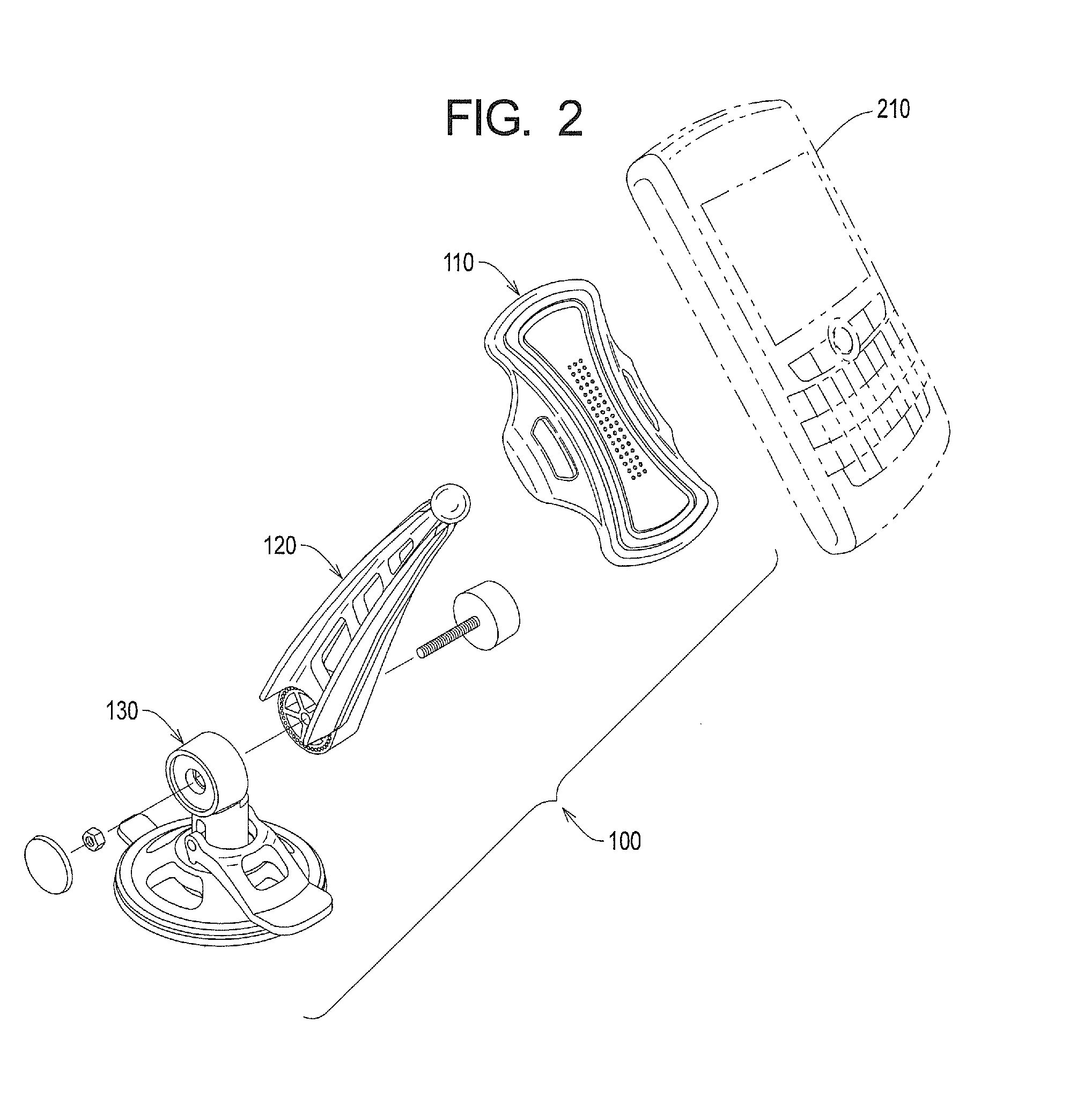
[0101]FIG. 2 is an exploded perspective view of the embodiment of the stand 100 shown in FIG. 1, but from a different angle than that shown in FIG. 1. In addition, FIG. 2 shows an exemplary portable electronic device 210 (in phantom) which may be used with the stand 100.
[0102]As will be discussed in more detail when referring to the other figures contained herein, the stand 100 permits adjustment of the viewing angle of the portable electronic device 210 via a ball-and-soc...
second embodiment
[0258]FIGS. 126-128 illustrate various views of a semi-spherical stand 12600. The semi-spherical stand 12600 includes a display platform 12610 and a base 12620.
[0259]A gripping pad 12640 attaches to a platform body 12650. As shown in FIG. 126, the gripping pad 12640 may be used to suspend a portable electronic device (shown in phantom). The display angle of the portable electronic device may be modified by changing the position of the display platform 12610 relative to the base 12620.
[0260]In one embodiment, the gripping pad 12640 may take the shape of a ring, so as to allow a cable to pass through its center. As shown in FIG. 128, the housing 12630 of the display platform 12610 includes an aperture 12810, which corresponds with the position of the gripping pad 12640. The aperture 12810 permits passage of a cable (not shown) therethrough. The cable may be attached to a portable electronic device that is suspended by the gripping pad 12640, so as to charge the portable electronic dev...
third embodiment
[0261]FIGS. 129-139 illustrate various views of a semi-spherical stand 12900, along with a portable electronic device. The semi-spherical stand 12900 includes a display platform 12910 and a base 12920.
[0262]A gripping pad 12940 attaches to a platform body 12950. The gripping pad 12940 may be used to suspend a portable electronic device (see FIGS. 131, 133 and 134).
[0263]The display platform 12910 and the base 12920 may be attached to one another gluing, ultrasonic welding or other well-known techniques. Alternatively, the display platform 12910 and the base 12920 may be formed of a single piece.
[0264]The base 12920 includes a plurality of facets and / or dimples 12960. As shown in FIGS. 131 and 133-137, the display angle of the portable electronic device may be modified by changing the position of the base 12960 and allowing the stand 12900 to come to rest in a position associated with one or more of the facets and / or dimples 19260.
[0265]FIGS. 140-143 illustrate various views of a sec...
PUM
 Abstract
Description
Claims
Application Information