Wireless communication network, method of generating neighbor list in the wireless communication network, and control device therefor

Inactive Publication Date: 2010-12-23
HITACHI LTD
View PDF8 Cites 11 Cited by
  • Summary
  • Abstract
  • Description
  • Claims
  • Application Information

AI Technical Summary

Benefits of technology

[0011]In accordance with the present invention, when a shill is desired from an existing system to a new system or when the new system is introduced while also maintaining the existing system, neighbor lists used so far in the existing system can be used in th

Problems solved by technology

The searching of the adjacent base stations imposes a heavy processing load on the mobile terminal.
Thus creation of neighbor lists of

Method used


Image

  • Wireless communication network, method of generating neighbor list in the wireless communication network, and control device therefor
  • Wireless communication network, method of generating neighbor list in the wireless communication network, and control device therefor
  • Wireless communication network, method of generating neighbor list in the wireless communication network, and control device therefor

Examples


Embodiment Construction

[0031]Embodiments of the present invention will be detailed in connection with illustrated embodiments.

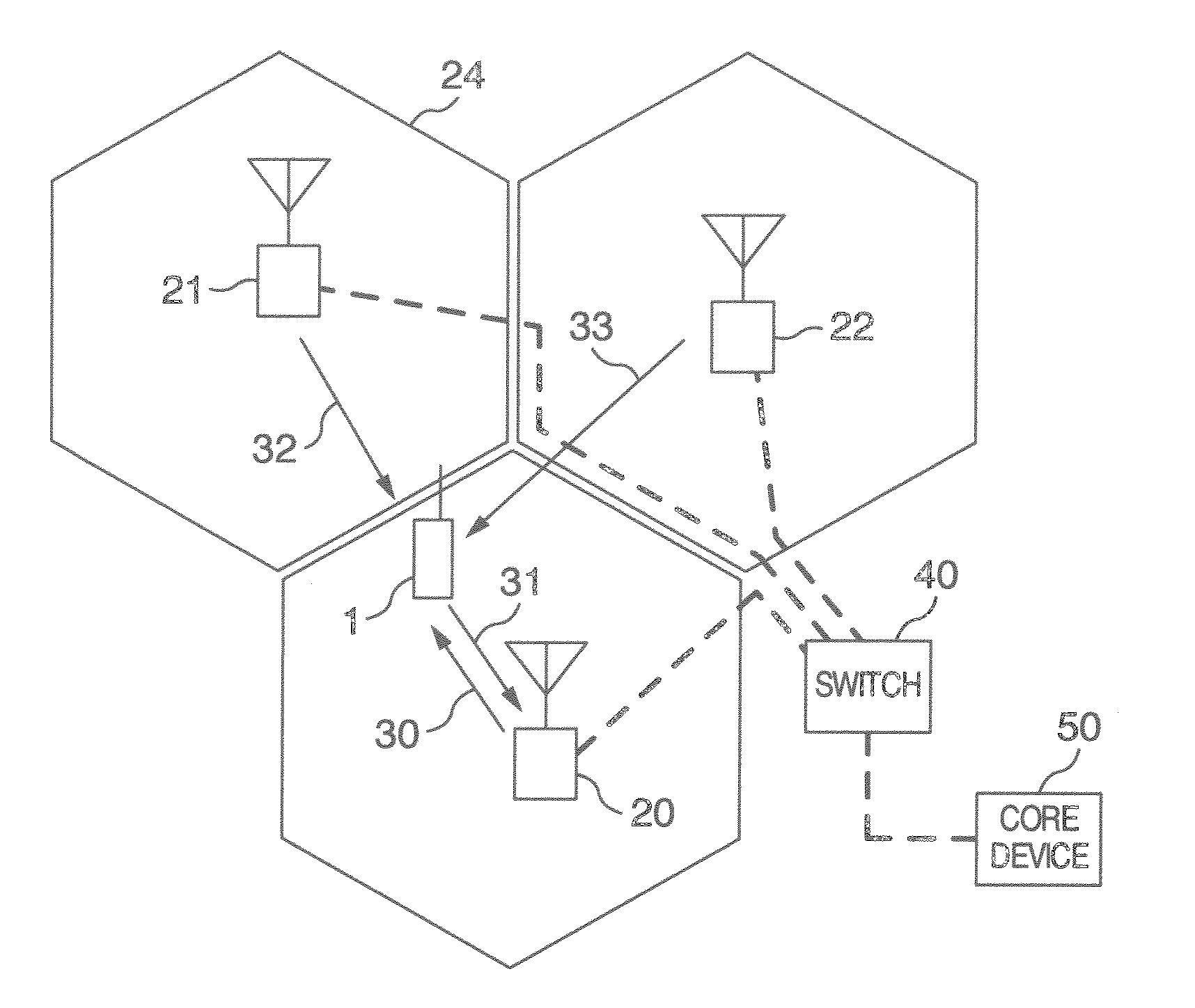
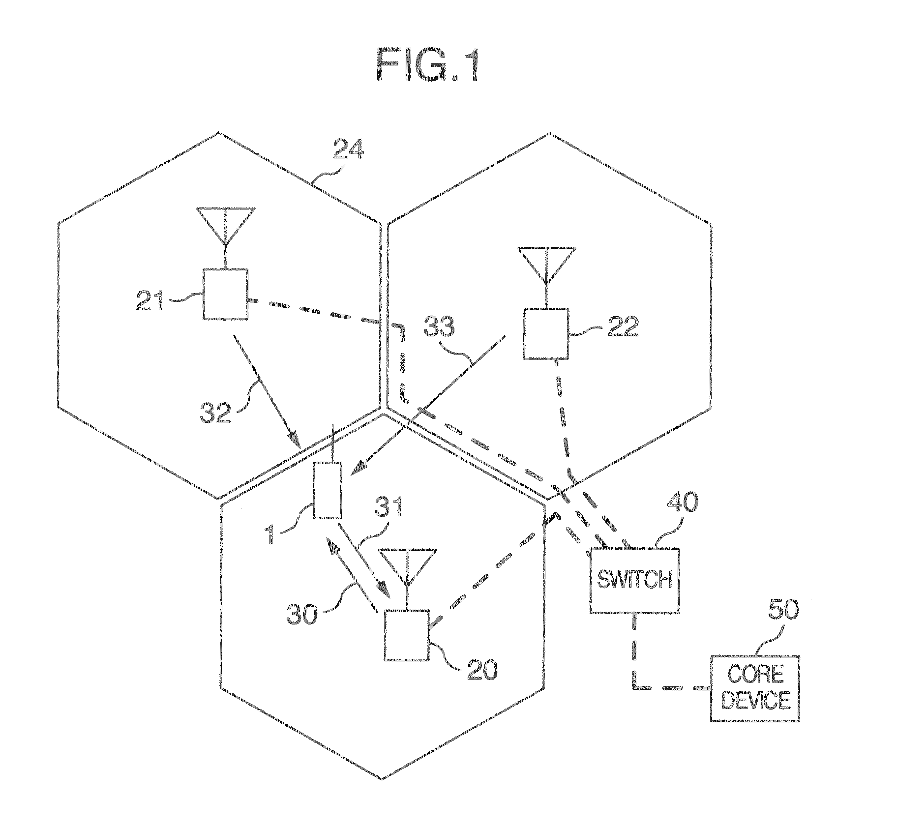
[0032]FIG. 1 shows an exemplary configuration of a mobile communication system to which the present invention is applied.

[0033]Base station devices 20 to 22 communicate with a core device 50 to be connected to a core network. A signal from the core device 50 is input to the base station device 20 via a switch 40. The base station device 20 converts the signal received from the core device 50 into a radio frequency signal and transmits a radio signal 30 as the converted signal to a mobile terminal 1. The mobile terminal 1 communicates with the core device 50 by receiving the radio signal 30 transmitted from the base station device 20 and performing signal processing operation over the radio signal to convert the signal to information.

[0034]Information generated by the mobile terminal 1, on the other hand, is converted to a radio frequency signal in the mobile terminal 1 and then tra...


PUM


Abstract

In a wireless communication system, a base station control device has following two steps on the basis of latitude/longitude information obtained from a GPS, that is, a first step of recognizing, from the positional information obtained from the GPS, the fact that base stations in new and old systems are installed at the same location, and a second step of linking a neighbor list of the old system to a neighbor list of the new system with use of the result of the first step.

Description

INCORPORATION BY REFERENCE[0001]The present application claims priority from Japanese application JP 09-129806 filed on May 29, 2009, the content of which is hereby incorporated by reference into this application.BACKGROUND OF THE INVENTION[0002]The present invention relates to a mobile wireless communication technique and more particularly, to a system parameter setting technique in the mobile wireless communication system.[0003]As a mobile wireless communication technique is advanced, a bit cost is being reduced. When a shift is desired from an existing system to a new system or when a new system is introduced while also maintaining an existing system, it becomes important to reduce an initial investment cost, introduce the new system more smoothly, and start the service of the new system more quickly. In order to remarkably reduce the initial investment cost, its key point is to utilize the resources of the existing system as much as possible. For example, use of a power supply o...

Claims


Application Information

Patent Timeline
IPC IPC(8): H04L12/28G01S19/12
CPCH04W8/26H04W88/08H04W36/0083H04W36/00835H04W36/0085
Inventor NAGANO, RUMIKOKUWAHARA, MIKIOYOSHIDA, AKIHIKO
Owner HITACHI LTD
Why Eureka
Try Eureka