A cooling water treatment system for refrigeration units in dry season
A technology for cooling water treatment and refrigeration units, applied in the field of cooling water treatment systems and cooling water treatment systems, can solve problems such as energy consumption, high noise, and impact on workers' health, increase operating equipment, avoid energy waste, and have a simple structure Effect
- Summary
- Abstract
- Description
- Claims
- Application Information
AI Technical Summary
Problems solved by technology
Method used
Image
Examples
Embodiment 1
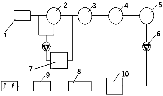
[0028] A cooling water treatment system for a refrigerating unit in a dry season, characterized in that it includes: a pump boat 1, a grit chamber 2, a machine tank 3, a siphon tank 4, a clean water tank 5, a clean water pump 6, a refrigerating unit 7, and an ion exchanger 8. The soft water pipe network 9 and the old refrigeration station 10, the grit chamber 2 is connected to the refrigeration unit 7, the refrigeration unit 7 is connected to the machine adding pool 3, and the machine adding pool 3 is connected to the siphon pool 4 The siphon pool 4 is connected with the clean water pool 5, the clean water pool 5 is connected with the old refrigeration station 10, and a clean water pump 6 is arranged between the clean water pool 5 and the old refrigeration station 10 , the old refrigeration station 10 is connected to the ion exchanger 8, and the ion exchanger 8 is connected to the soft water pipe network 9.
[0029] A cooling water treatment system for refrigerating units in d...
Embodiment 2
[0038] A cooling water treatment system for a refrigerating unit in a dry season, characterized in that it includes: a pump boat 1, a grit chamber 2, a machine tank 3, a siphon tank 4, a clean water tank 5, a clean water pump 6, a refrigerating unit 7, and an ion exchanger 8. The soft water pipe network 9 and the old refrigeration station 10, the grit chamber 2 is connected to the refrigeration unit 7, the refrigeration unit 7 is connected to the machine adding pool 3, and the machine adding pool 3 is connected to the siphon pool 4 The siphon pool 4 is connected with the clean water pool 5, the clean water pool 5 is connected with the old refrigeration station 10, and a clean water pump 6 is arranged between the clean water pool 5 and the old refrigeration station 10 , the old refrigeration station 10 is connected to the ion exchanger 8, and the ion exchanger 8 is connected to the soft water pipe network 9.
[0039] The default temperature range of the condenser in the refrige...
Embodiment 3
[0050] A cooling water treatment system for a refrigerating unit in a dry season, characterized in that it includes: a pump boat 1, a grit chamber 2, a machine tank 3, a siphon tank 4, a clean water tank 5, a clean water pump 6, a refrigerating unit 7, and an ion exchanger 8. The soft water pipe network 9 and the old refrigeration station 10, the grit chamber 2 is connected to the refrigeration unit 7, the refrigeration unit 7 is connected to the machine adding pool 3, and the machine adding pool 3 is connected to the siphon pool 4 The siphon 4 pool is connected with the clean water pool 5, the clean water pool 5 is connected with the old refrigeration station 10, and a clean water pump 6 is arranged between the clean water pool 5 and the old refrigeration station 10 , the old refrigeration station 10 is connected to the ion exchanger 8, and the ion exchanger 8 is connected to the soft water pipe network 9.
[0051] The default temperature of the condenser in the refrigeration...
PUM
 Abstract
Description
Claims
Application Information
 - R&D
- Intellectual Property
- Life Sciences
- Materials
- Tech Scout
- Unparalleled Data Quality
- Higher Quality Content
- 60% Fewer Hallucinations
Browse by: Latest US Patents, China's latest patents, Technical Efficacy Thesaurus, Application Domain, Technology Topic, Popular Technical Reports.
© 2025 PatSnap. All rights reserved.Legal|Privacy policy|Modern Slavery Act Transparency Statement|Sitemap|About US| Contact US: help@patsnap.com

