A high-speed vortex flow gas separation device

A technology of flowing gas and separation devices, applied in the field of gas separation and liquefaction devices, can solve the problems of small centrifugal force, high manufacturing and operating costs, complex structure and process flow, etc., and achieve high recovery efficiency, less energy loss, high-efficiency separation or The effect of the liquify effect

Active Publication Date: 2021-12-28
闫家义 +1
View PDF14 Cites 0 Cited by
  • Summary
  • Abstract
  • Description
  • Claims
  • Application Information

AI Technical Summary

Problems solved by technology

The main disadvantages of these two technical methods are: complex structure and process flow of the device, high manufacturing and operating costs, separation and liquefaction efficiency are greatly affected by changes in the working conditions of the imported gas source
The vortex airflow moving in the circular cross-section flow channel has a small centrifugal force in the area around the center of the cross-section, and there is a vortex stagnation area with a small rotational momentum, and the droplets in this area are subjected to a small centrifugal force. It is not easy to be thrown to the walls of the expansion section and the working section of the nozzle and shunted out by the separation port, thus preventing the further improvement of the separation efficiency of the entire device

Method used


Image

  • A high-speed vortex flow gas separation device
  • A high-speed vortex flow gas separation device
  • A high-speed vortex flow gas separation device

Examples


Embodiment

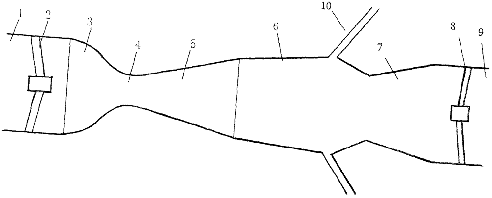
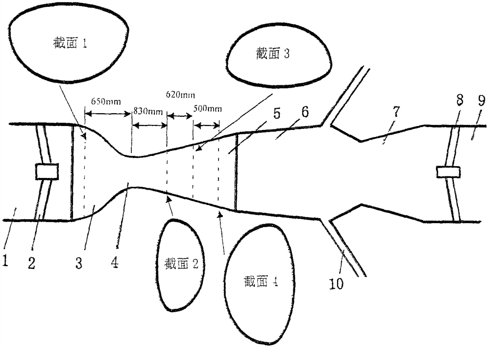
[0048] Embodiment Non-concentric variable section GWF device ( Figure 12 , image 3 shown)

[0049] Location of use: A gas gathering station in Kuqa, southern Xinjiang

[0050] Operation time: October 1, 2012

[0051] Raw gas initial conditions and requirements:

[0052] 1. Entry pressure: 2.0~2.2MPa.g

[0053] 2. Entry temperature (T0): ≤30°C

[0054] 3. Capacity: 6~15×10 4 N m 3 / day (0.1MPa, at 20°C)

[0055] 4. Water dew point (under outlet pressure): ≤-15°C

[0056] 5. Feed gas components (the sum of carbon-3 and above components is 5.52%)

[0057] components Gas composition (v%) components Gas composition (v%) methane 78.19 Isopentane 0.12 ethane 10.20 n-pentane 0.11 propane 3.88 Nitrogen 3.29 Isobutane 0.47 carbon dioxide 2.8 n-butane 0.94 Relative density 0.706

[0058] Set device design parameters (with a processing capacity of 13×10 4 N m 3 / day is set for standard working conditions)

[0...


PUM


Abstract

A high-speed vortex flow gas separation device, comprising a device inlet port (1), a device nozzle (3, 4, 5, 6), a device diffuser section (7) connected to the device nozzle, and a device Outlet end (9); said device nozzle (3, 4, 5, 6) is sequentially composed of constriction section (3), throat (4), expansion section (5) and working section (6); The cross-sections of the device nozzles (3, 4, 5, 6) are not concentric circular cross-sections, but non-concentric deformed cross-sections, which eliminate the vortex stagnation in the central area of ​​each cross-section of the flow channel of the device nozzles zone; the high-speed vortex flow gas separation device obtains a dry gas production rate of 98.5%-99.5%; in the feed gas, the total proportion of liquid hydrocarbons above carbon-3 is 5.52%, through the high-speed After separation by the vortex flow gas separation device, the removal amount of liquid hydrocarbons above carbon-3 is 4.02%-5.02%.

Description

technical field [0001] The invention belongs to a gas separation and liquefaction device, in particular a non-concentric variable cross-section controllable vortex type high-speed vortex flow gas separation device that greatly improves separation efficiency. For the convenience of description, it is referred to as a non-concentric variable cross-section GWF device. , suitable for advanced technical equipment for gas purification and liquefaction industries such as natural gas, petrochemical, metallurgy, medical treatment and purified water. Background technique [0002] At present, in the actual engineering applications of various industries such as natural gas, petrochemical, metallurgy, medical treatment and purified water, there are mainly two technical methods for gas separation and liquefaction. One is the widely used cryogenic separation method of expander refrigeration. This method is to cool down the gas that has been compressed to a certain pressure through a heat ...

Claims


Application Information

Patent Timeline
Patent Type & Authority Patents(China)
IPC IPC(8): B01D53/00B01D5/00B01D45/16C10L3/10
CPCB01D5/0033B01D45/16B01D53/002C10L3/10C10L3/101C10L3/106B01D2256/245C10L2290/54
Inventor 闫家义刘一维
Owner 闫家义
Why Eureka
Try Eureka