

Optical fiber connector and adapter
a technology of optical fiber and adapter, which is applied in the direction of optics, instruments, optical light guides, etc., can solve the problems of increasing the risk of damage and user inability to noti
- Summary
- Abstract
- Description
- Claims
- Application Information
AI Technical Summary
Problems solved by technology
Method used
Image

Examples
first embodiment
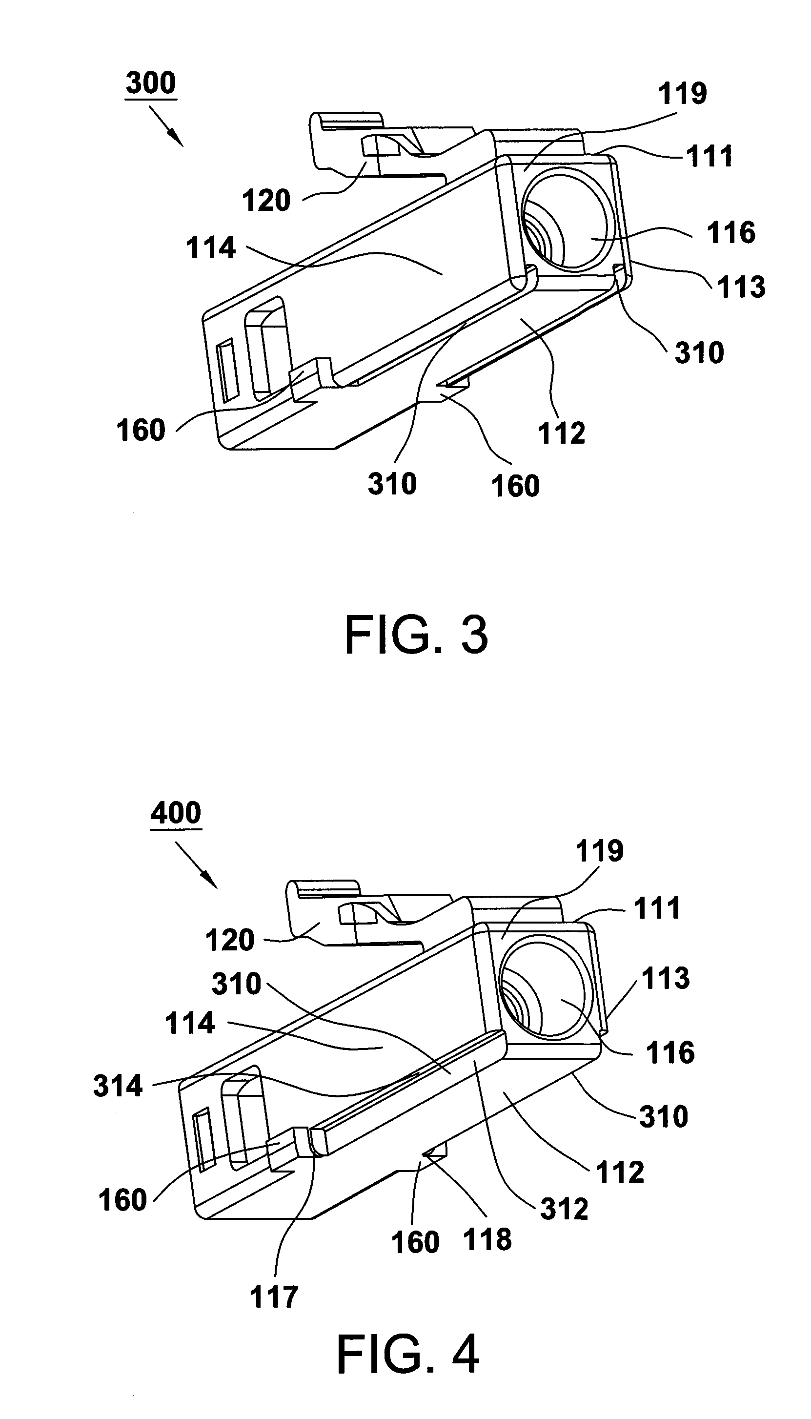
[0025]Referring to FIG. 3, the optical fiber connector 300 according to the present invention is similar to the optical fiber connector 100 of FIG. 1 and also includes the housing 110, latch 120 and protrusions 160. However, the opening 116 of the housing 110 for the connector 300 is circular. For simplicity, the ferrule of the connector 300 in FIG. 3 is omitted. In addition, the connector 300 is further provided with rectangular indentations 310 that are positioned on the edges of the bottom side-wall 112 and adjacent to the right side-wall 113 and left side-wall 114, respectively. The indentations 310 extend from the front end 119 of the housing 110.
second embodiment
[0026]Referring to FIG. 4, the optical fiber connector 400 according to the present invention is similar to the optical fiber connector 300 of FIG. 3 and includes the housing 110, latch 120 and protrusions 160. The opening 116 of the housing 110 for the connector 400 is circular. For simplicity, the ferrule of the connector 400 in FIG. 4 is also omitted. However, the indentations 310 for the connector 400 are arranged on different positions, wherein one of the indentations 310 is positioned on the common boundary 117 between the bottom side-wall 112 and left side-wall 114, and the other is positioned on the common boundary 118 between the bottom side-wall 112 and right side-wall 113. These indentations 310 also extend from the front end 119 of the housing 110. Each of the indentations 310 has at least two walls 312 and 314 that are parallel to the left side-wall 114 and bottom side-wall 112, respectively.
third embodiment
[0027]Referring to FIG. 5, the optical fiber connector 500 according to the present invention is similar to the optical fiber connector 100 of FIG. 1 and also includes the housing 110, latch 120 and protrusions 160. For simplicity, the ferrule of the connector 500 in FIG. 5 is omitted. In addition, a cut face 510 is formed on the common boundary 117 between the bottom side-wall 112 and left side-wall 114 and another cut face 510 is formed on the common boundary 118 between the bottom side-wall 112 and right side-wall 113. The cut faces 510 can be plane.
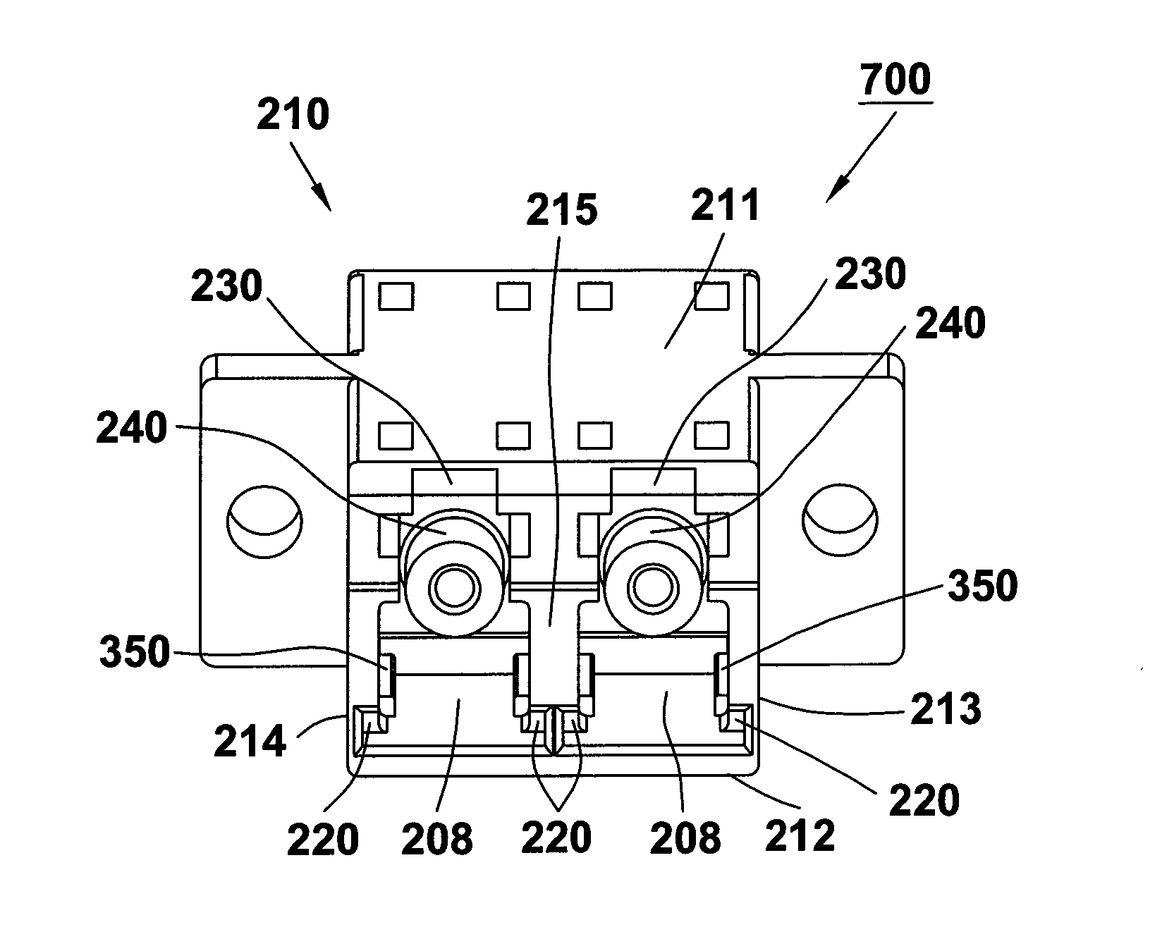
[0028]Referring to FIG. 6, the optical fiber adapter 600 according to the first embodiment of the present invention is similar to the optical fiber adapter 200 of FIG. 2 and also includes the housing 210 and hollow cylinder 240. However, the cylinder 240 has a round cross-sectional shape. In addition, the adapter 600 is further provided in the right and left axial cavities with rectangular protrusions 350 mating with the indentations ...
PUM
 Abstract
Description
Claims
Application Information