Optical subassembly for coupling light into an optical waveguide

Active Publication Date: 2010-12-30
LUMENTUM OPERATIONS LLC
View PDF14 Cites 19 Cited by
  • Summary
  • Abstract
  • Description
  • Claims
  • Application Information

AI Technical Summary

Benefits of technology

[0011]In accordance with another aspect of the invention there is further provided a method f

Problems solved by technology

One of the problems in fiberoptic communications is that optical feedback, or backreflection from the optical fiber to the laser light source affects the laser operation and gives rise to jitter in the timing of the rising and falling edges of the modulated optical signal.
One drawback of these prior art approaches is increased sensitivity to optical m

Method used


Image

  • Optical subassembly for coupling light into an optical waveguide
  • Optical subassembly for coupling light into an optical waveguide
  • Optical subassembly for coupling light into an optical waveguide

Examples


Embodiment Construction

[0025]While the present teachings are described in conjunction with various embodiments and examples, it is not intended that the present teachings be limited to such embodiments. On the contrary, the present teachings encompass various alternatives, modifications and equivalents, as will be appreciated by those of skill in the art.

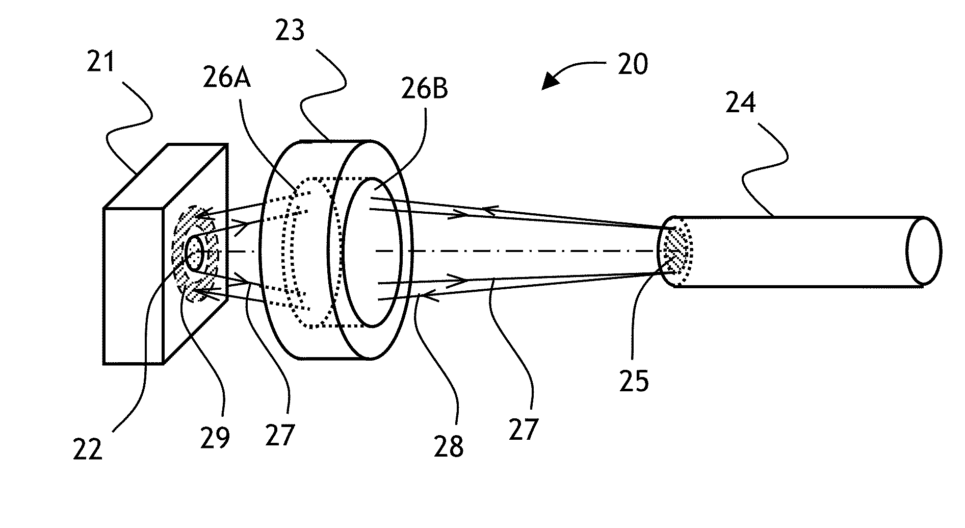
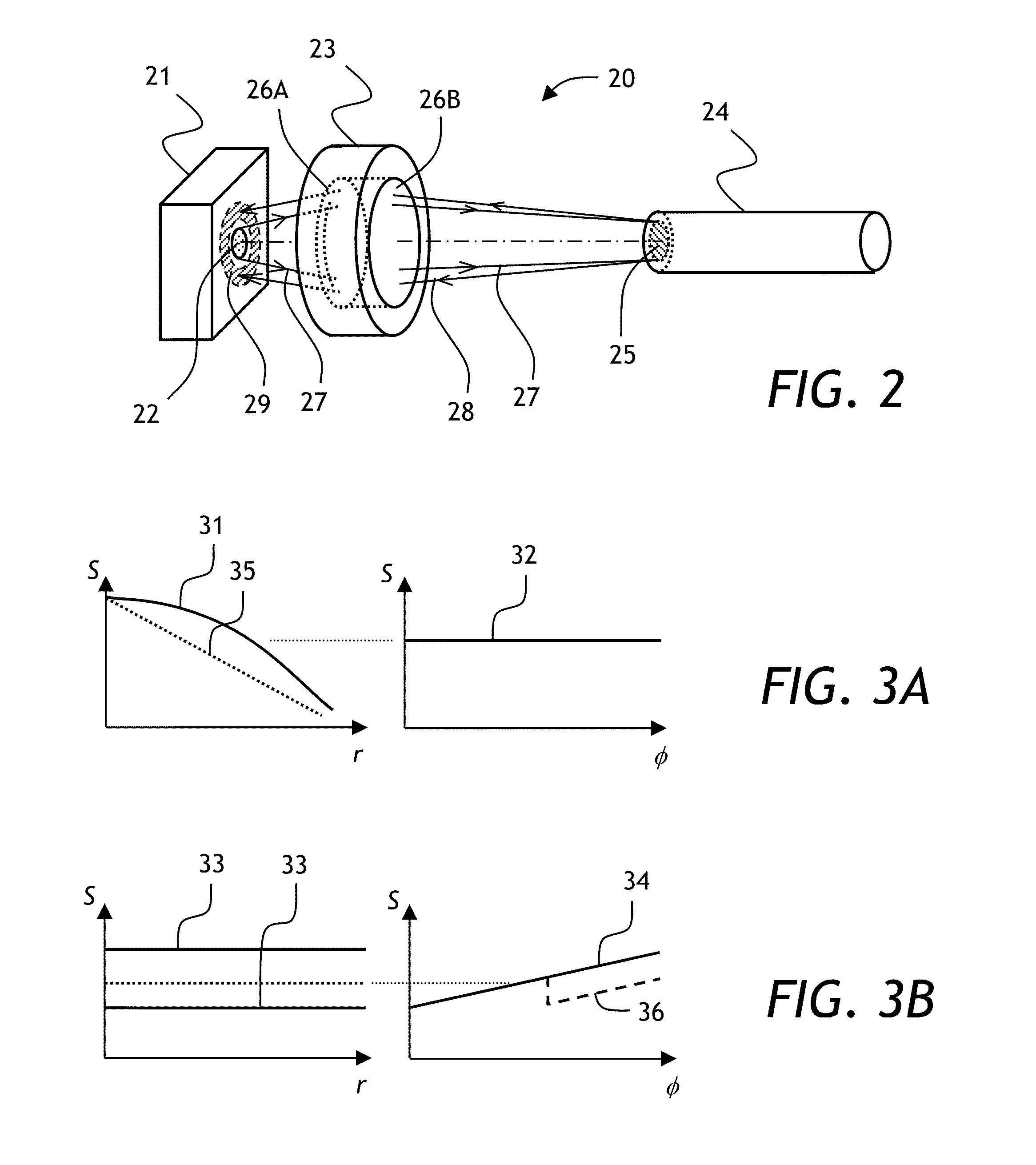
[0026]Referring to FIG. 2, an optical subassembly 20 of the present invention includes a light source, such as a vertical cavity surface-emitting laser (VCSEL) 21 having an aperture 22, and a multimode optical fiber 24 having an aperture 25, with a lens 23 disposed therebetween. The VCSEL21, the lens 23, and the multimode optical fiber 24 are coaxially disposed. The lens 23 has surfaces 26A and 26B. The surface 26A has a surface profile, or so called surface sag, described by two sag components: an aspheric component and a helical component. In operation, light emitted by the aperture 22 of the VCSEL 21 is focused into the aperture 25 of the fiber 24, as ...


PUM


Abstract

An optical subassembly for low-feedback coupling of light from a light source into an optical waveguide such as an optical fiber is described. The optical subassembly has an aspherical lens with surface sag having a rotationally symmetrical sag component without having a cone sag component, and a rotationally asymmetrical helical component for reducing coupling of light reflected from the optical fiber tip back into the laser aperture by causing a significant portion of the reflected light to encircle the laser aperture. The lens shape and the height of the helix are selected so that tight focusing onto the fiber tip is preserved, while the optical feedback is reduced.

Description

CROSS-REFERENCE TO RELATED APPLICATIONS[0001]The present invention claims priority from U.S. Patent Appln. No. 61 / 220,846 filed Jun. 26, 2009, which is incorporated herein by reference for all purposes.TECHNICAL FIELD[0002]The present invention relates to optical subassemblies for light coupling, and in particular to optical subassemblies for coupling light from a backreflection-sensitive light source into an optical waveguide.BACKGROUND OF THE INVENTION[0003]In fiberoptic communications, light from a light source, such as a laser or a light emitting diode (LED), is modulated with a data stream at a high rate and transmitted through a length of an optical fiber between two or more geographical locations. The laser is usually coupled to the optical fiber using a lens.[0004]One of the problems in fiberoptic communications is that optical feedback, or backreflection from the optical fiber to the laser light source affects the laser operation and gives rise to jitter in the timing of th...

Claims


Application Information

Patent Timeline
IPC IPC(8): G02B6/32
CPCG02B6/4207G02B3/02
Inventor GRAHAM, LUKE
Owner LUMENTUM OPERATIONS LLC
Why Eureka
Try Eureka