Fabrication of collimators employing optical fibers fusion-spliced to optical elements of substantially larger cross-sectional areas

a collimator and optical fiber technology, applied in the field of fiber collimators, can solve the problems of undesirable use of adhesives in the optical path of such devices, difficult splicing of optical fibers to much larger optical elements, and high cost, so as to improve power handling characteristics, reduce back-reflection, and improve the effect of fusion splicing accuracy

Inactive Publication Date: 2002-04-11
BERNARD PIERRE +4
View PDF1 Cites 6 Cited by
  • Summary
  • Abstract
  • Description
  • Claims
  • Application Information

AI Technical Summary

Benefits of technology

[0012] In accordance with the present invention, a fiber collimator is provided, having reduced back-reflection, improved pointing accuracy, and improved power handling characteristics. The fiber collimator comprises at least one optical fiber fusion-spliced to an optical element, such as a collimator lens. The optical element is constructed from an optical material which has an index of refraction nearly equal to the index of refraction of the optical fiber to which it is fusion-spliced For commercial reasons, pure fused silica glass is preferred. In addition, the fiber collimator may comprise at least one fiber fusion-spliced to an optical element other than a collimator lens, such as a plano-plano "pellet" which is subsequently assembled jointly with a separate collimator lens. This latter configuration is especially useful in creating collimators with long optical path lengths and associated large collimated beam diameters. The utilization of an optical pellet provides all the advantages of reduced back-reflection and improved power handling while reducing the required lens thickness in long focal length collimators.
[0014] By attaching fibers directly to other optical components without using epoxies or special termination techniques, costs are reduced, environmental stability is improved, alignment accuracy is enhanced, pointing accuracy is improved, and power handling is significantly increased.

Problems solved by technology

Splicing an optical fiber to a much larger optical element is more challenging.
However, this is an extremely complicated method and has limited applications.
The use of adhesives in the optical path of such devices is undesirable due to the chance of degradation of the adhesive over time.
This phenomenon, known as back-reflection, is a source of noise in many communications networks, and effectively limits transmission bandwidth of such communications networks.
Back-reflection resulting from simple butt-end coupling reduces the optical output and efficiency.
In optical communication systems, back-reflection also has a detrimental impact on the BER (bit error rate) and the SNR (signal-to-noise ratio).
Due to its uncontrolled generation and propagation, power reflected back in the fiber is considered excess noise when detected.
However, these existing technologies for assembling collimators require very labor intensive active alignment techniques.
By then, the beam is so large that the amount of light that can return to the fiber core is extremely small.

Method used


Image

  • Fabrication of collimators employing optical fibers fusion-spliced to optical elements of substantially larger cross-sectional areas
  • Fabrication of collimators employing optical fibers fusion-spliced to optical elements of substantially larger cross-sectional areas
  • Fabrication of collimators employing optical fibers fusion-spliced to optical elements of substantially larger cross-sectional areas

Examples


second embodiment

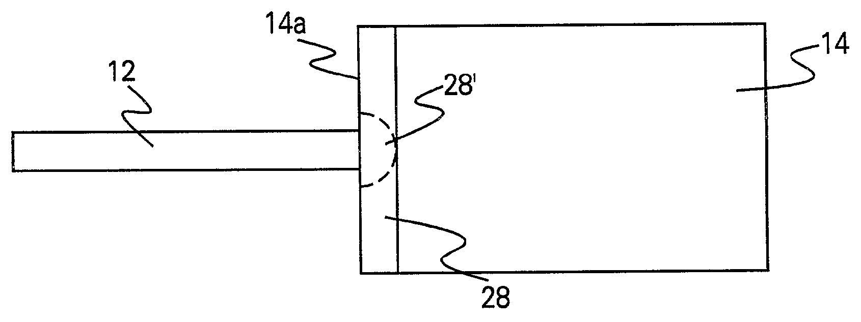
[0035] In a second embodiment, the fusion occurs starting with contact of all of the optical components and the components are never separated during the fusion-splicing.

[0036] In a third embodiment, all of the optical components are brought into contact, then pulled back after alignment, and then fusion-spliced as in the first embodiment.

[0037] Qualification of the interface is accomplished by measuring the back reflection of light through the system as well as mechanical testing.

[0038] There are no practical limitations in using this technique with respect to size mismatch, or the absence of a mismatch, or in cross-sectional geometry.

[0039] Any multiple pieces of optical elements, whether comprising an inorganic glass or an organic polymer, can be fused using the method of the present invention. The most common application will be fusion of single mode fibers to optoelectronic or telecommunications devices. Fusion-splicing in accordance with the teachings herein virtually eliminat...

first embodiment

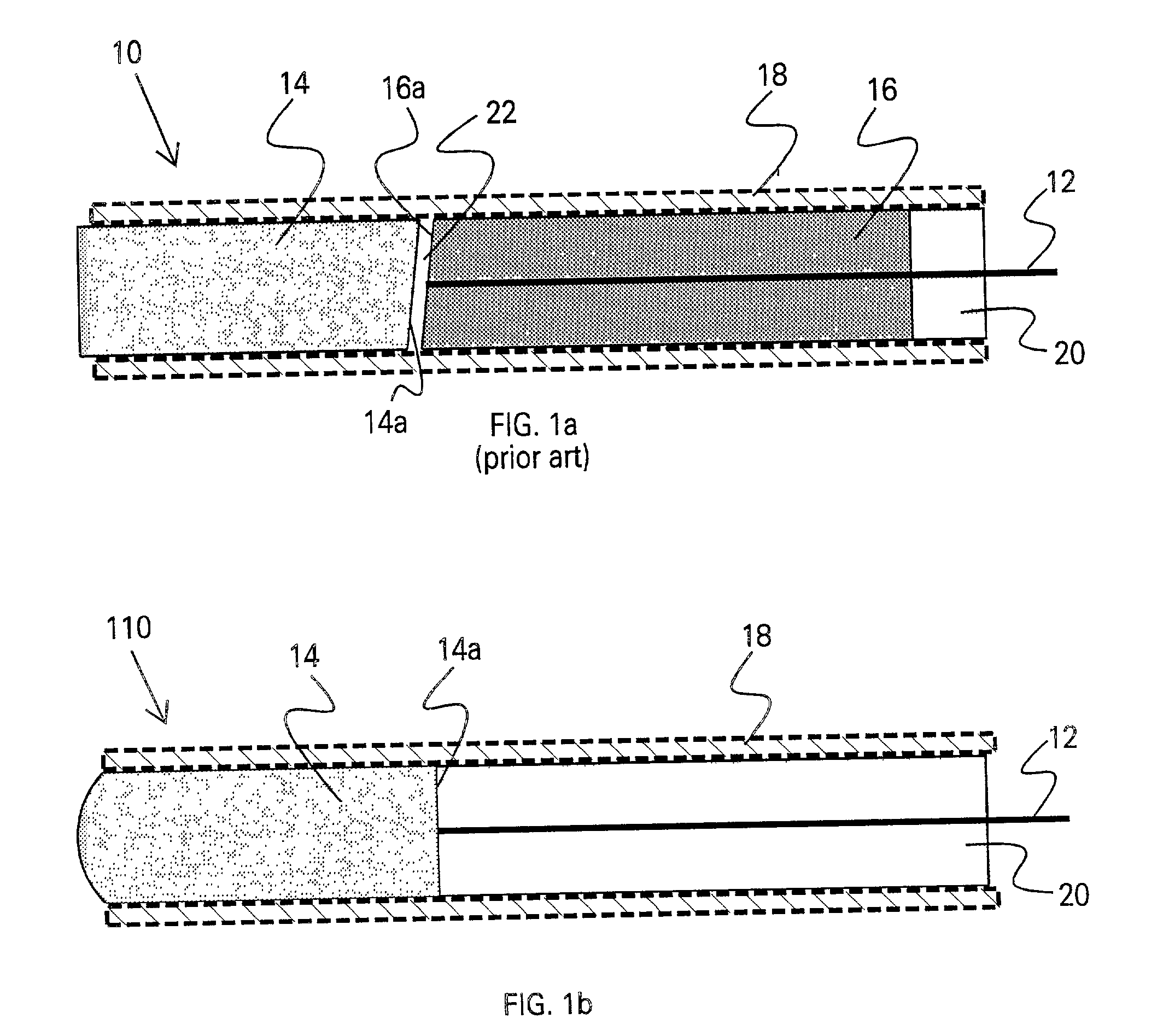
[0053] In the first embodiment, the two components (e.g., optical fiber(s) and optical element) are aligned but separated by a space (typically a few millimeters), the laser beam is turned on to form the softening region, and the surface of the optical fiber(s) is brought in contact with the softening region of the optical element, the contact resulting in heat transfer to the surface of the optical fiber(s), which then softens, thereby achieving the fusion-splicing.

[0054] In the second embodiment, the two components (e.g., optical fiber(s) and optical element) are first brought into contact and the laser beam is then turned on to form the softening region where the two components are in contact to achieve the fusion-splicing.

third embodiment

[0055] In the third embodiment, the two components (e.g., optical fiber(s) and optical element) are aligned, then brought into contact, then separated by a space (typically a few millimeters), the laser beam is turned on to form the softening region, and the surface of the optical fiber(s) is brought in contact with the softening region of the optical element, the contact resulting in heat transfer to the surface of the optical fibers, which then softens, thereby achieving the fusion-splicing.

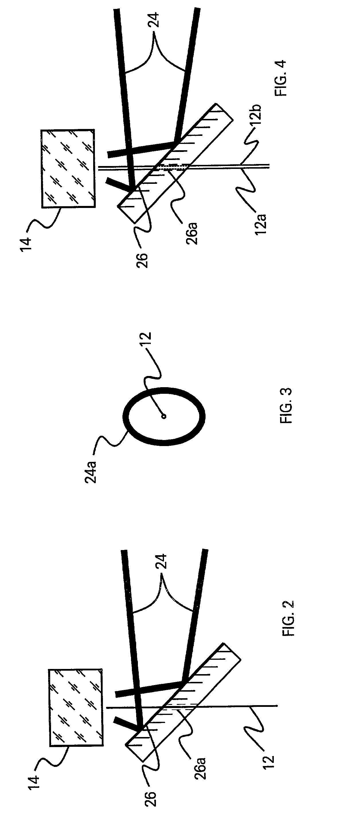
[0056] For fusion-splicing typical inorganic glasses, such as silica, a CO.sub.2 laser, which operates in the range 9 to 11 .mu.m, is preferred, since silica-based glasses have very large absorption coefficient. Other optical materials typically have a large absorption in the infrared, and accordingly, lasers operating in another region of the IR spectrum may be used with such other optical materials.

[0057] The laser beam is collinear and grazes the optical fiber(s). This can be accomplished in...


PUM

PropertyMeasurementUnit
thicknessaaaaaaaaaa
thicknessaaaaaaaaaa
wavelength regionaaaaaaaaaa

Abstract

A fiber collimator is provided, comprising at least two optical components, one of the optical components (e.g., an optical element such as a collimating lens or a plano-plano pellet) having a surface that has a comparatively larger cross-sectional area than the surface of the other optical component(s) (e.g., at least one optical fiber). The optical components are joined together by fusion-splicing, using a laser. A gradient in the index of refraction is provided in at least that portion of the surface of the optical element to which the optical fiber(s) is fusion-spliced or at the tip of the optical fiber. The gradient is either formed prior to or during the fusion-splicing. Back-reflection is minimized, pointing accuracy is improved, and power handling ability is increased.

Description

[0001] The present application is a continuation-in-part of application Ser. No. 09 / 118,033, filed Jul. 17, 1998, and is related (1) to co-pending application Ser. No. ______, filed ______ [D-98032A], which is also a continuation-in-part application of the '033 application, and (2) to co-pending application Ser. No. ______, filed ______ [D-98032C], which is a divisional application of the '033 application.[0002] The present invention relates generally to optoelectronics involving optical components of significantly different cross-sectional areas, such as optical fibers joined to optical elements such as lenses, filters, gratings, prisms, and the like, and, more particularly, to fiber collimators.[0003] Fiber collimators find extensive use in optoelectronics, particularly in the coupling of light from (to) an optical fiber to (from) a collimating lens. Fiber collimators are basic components of telecommunication products such as isolators, mechanical switches, couplers, circulators, ...

Claims


Application Information

Patent Timeline
Patent Type & Authority Applications(United States)
IPC IPC(8): B23K26/00G02B3/00G02B6/24G02B6/255G02B6/26G02B6/32G02B6/42
CPCG02B6/24G02B6/2551G02B6/4204G02B6/32G02B6/262G02B6/255
Inventor BERNARD, PIERREFITCH, MARK A.FOURNIER, PAULHARRIS, MARC FARRELLWALTERS, WILLIAM P.
Owner BERNARD PIERRE
Why Eureka
Try Eureka