
Termination Of Optical Fiber With Low Backreflection

a technology of optical fibers and backscattering, applied in the field of fiber optics, can solve the problems of low reflectivity, high touch or backscattering of nearby objects, and affect the accuracy and resolution of shape/position sensing, etc., and achieve the effect of low reflectivity

Active Publication Date: 2015-08-06
OFS FITEL LLC
View PDF8 Cites 3 Cited by
  • Summary
  • Abstract
  • Description
  • Claims
  • Application Information

AI Technical Summary

Benefits of technology

The invention is about creating structures and methods to end optical fibers with low backreflection. These structures meet several requirements: low reflectivity, insensitive to touch and external surfaces, compact, strong, and can be made in a way that allows for scalability.

Problems solved by technology

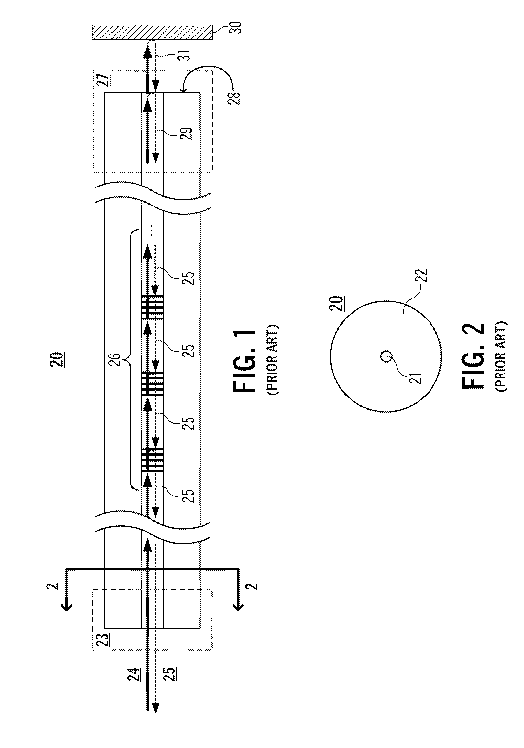
A strong reflection from the tip can adversely saturate the detector used to detect distributed backreflection, and consequently impair the accuracy and resolution of the shape / position sensing.
While conventional methods for terminating a sensor fiber are capable of reducing backreflection from the fiber tip, the sensor performance can become highly sensitive to touch or to backreflection or backscattering from nearby objects.
Light emitted from the sensor fiber tip propagates through the absorbing structure, and is attenuated by such an extent that reflection from nearby objects becomes insignificant.
First, the attachment of a light-absorbing structure to the fiber tip affects the positional accuracy of the sensor because of the lack of a sensing element (e.g., Bragg grating) in the appended structure. The light-absorbing structure has to have a length of at least a few millimeters in order to provide sufficient suppression of light emitted from the fiber tip. Thus, the positional accuracy of the sensor tip is limited by the length of the added structure.
Second, the light-absorbing structure typically has a refractive index that is different from that of silica glass fiber. Therefore, in order to suppress backreflection from the interface between the sensor fiber and the light-absorbing structure, a special splicing technique is needed, involving the use of a thermal diffusion technique to achieve index matching. The special splicing technique calls for individual processing of each fiber sensor, thus making batch processing difficult. Further, the strength of the sensor tip is compromised. The presence of the spliced component means that the sensor tip is increasingly prone to breakage / fracture as it is passed through tight bends.

Method used


Image

  • Termination Of Optical Fiber With Low Backreflection
  • Termination Of Optical Fiber With Low Backreflection
  • Termination Of Optical Fiber With Low Backreflection

Examples


Embodiment Construction

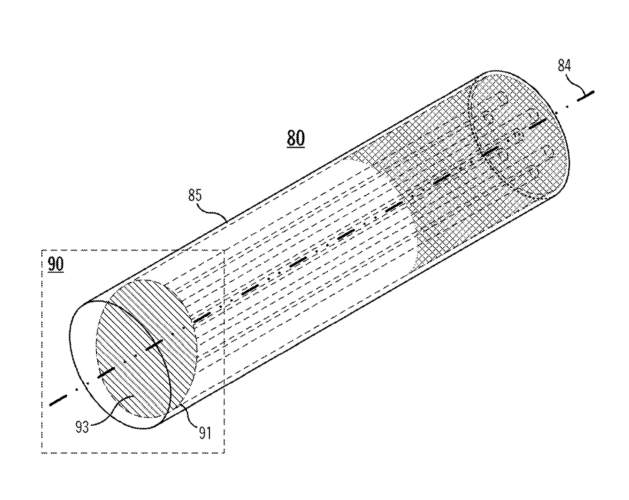
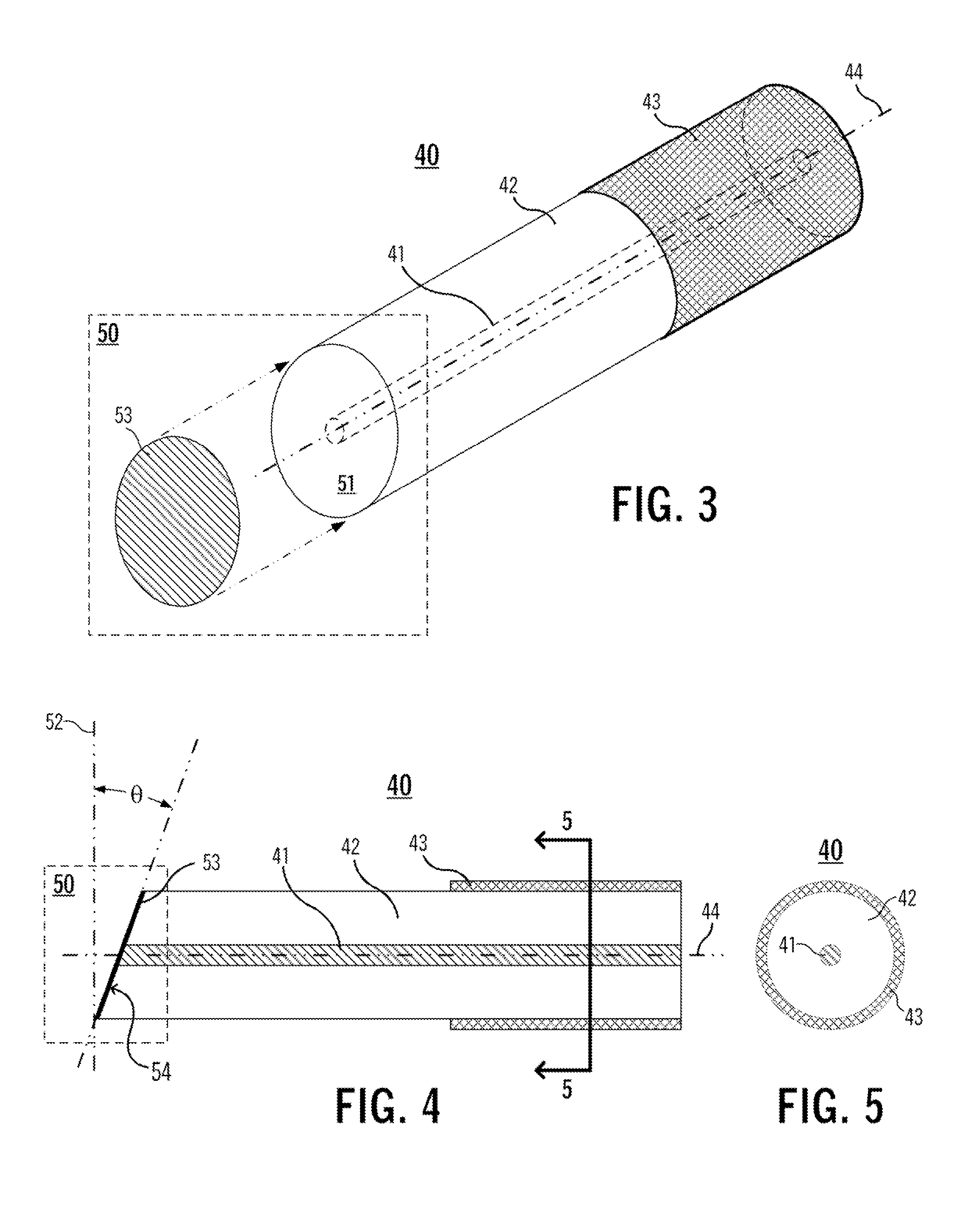
[0026]Aspects of the present invention are directed to structures and techniques for terminating a sensor fiber so as to suppress backreflection from the fiber tip. A termination structure in accordance with the aspects of the invention described herein is extremely compact, having a diameter that is the same as the sensor fiber and a length that is shorter than half the fiber diameter. In addition, the described termination structure is insensitive to proximity to, or contact with, external objects; has the same mechanical strength as the sensor fiber; and is highly suitable for volume production.

[0027]FIG. 1 shows a simplified, generic cross-section diagram of a single-core sensor fiber 20, and FIG. 2 shows a cross-section diagram through the plane 2-2. Sensor fiber 20 comprises a core 21 and cladding 22 that provide a light waveguide along the length of the fiber 20.

[0028]A sensing apparatus (not shown) is connected to the fiber's tail end 23. A reference light input 24 is launch...


PUM


Abstract

A technique is described for terminating an optical fiber with low backreflection. At a selected end of the optical fiber segment, an endface is formed at a selected angle relative to the fiber axis. A suitable material is deposited onto the angled endface to form an angled reflective surface. The angled reflective surface is configured such that light propagating along the waveguide to the selected end of the optical fiber segment is reflected back into the optical fiber segment at an angle that prevents coupling of the reflected light into the fiber core. The reflected light is dissipated along the length of the fiber segment.

Description

BACKGROUND OF THE INVENTION[0001]1. Field of the Invention[0002]The present invention relates generally to the field of fiber optics, and in particular to systems and techniques for terminating an optical fiber with low backreflection.[0003]2. Background Art[0004]In a fiber-optic sensor, a reference light is launched into a sensor fiber and the resulting backreflected light is detected and analyzed. A fiber-optic sensor can be used, for example, to detect changes in shape and / or position based on the measurement of the amplitude / phase of distributed backreflection along the length of the sensor fiber. In a shape / position sensor, and in other sensor applications, it is of utmost importance to suppress backreflection coming from the tip of the sensor fiber. A strong reflection from the tip can adversely saturate the detector used to detect distributed backreflection, and consequently impair the accuracy and resolution of the shape / position sensing.[0005]While conventional methods for ...

Claims


Application Information

Patent Timeline
IPC IPC(8): G02B6/26
CPCG02B6/262G02B6/241G01D5/35383G01D5/35316G01D5/35374A61B2018/2272G02B6/4214G02B6/00G02B6/4206
Inventor ABEDIN, KAZI SDIGIOVANNI, DAVID JWESTBROOK, PAUL S
Owner OFS FITEL LLC
Learn More