Optical coupling system that reduces back reflection and improves mode matching in forward optical coupling using perturbations at a reflective surface

a back reflection and optical coupling technology, applied in the field of optical communication modules, can solve the problems of reducing the performance of laser light sources, increasing the complexity and cost of transceiver packaging, and optical isolators that may not have the desired effect, etc., and achieve the effect of reducing back reflections

Active Publication Date: 2017-12-12
FOXCONN INTERCONNECT TECHNOLOGY LIMITED
View PDF13 Cites 6 Cited by
  • Summary
  • Abstract
  • Description
  • Claims
  • Application Information

AI Technical Summary

Benefits of technology

[0006]The inventive principles and concepts are directed to an optical coupling system for coupling a light beam produced by a light source onto an end face of an optical waveguide and a method. The optical coupling system comprises a flat surface positioned along an optical pathway of the optical coupling system and a plurality of perturbations disposed on an outer side of the flat surface. A light beam propagating along an optical pathway of the optical coupling system in a first direction is incident on an inner side of the flat surface having the perturbations formed therein. Each perturbation has a localized sagittal (sag) profile that provides a localized refractive effect on a portion of the light beam that is incident on the flat surface to form a respective light beam portion at a predetermined plane. The perturbations are shaped, sized and positioned such that a predetermined aggregated refractive effect of partially or fully overlapping all of the respective light beam portions at the predetermined plane forms a complex light beam shape at the predetermined plane that is different in shape from respective shapes of each of the respective light beam portions. The complex light beam shape is preselected to match one or more light modes of the light beam emitted by the light source with one or more light modes of the optical fiber. The complex light beam shape can also be preselected to reduce back reflections of the light beam from the end face of the optical waveguide into the light source.

Problems solved by technology

Back reflection increases RIN and degrades the performance of the laser light source.
The optical isolator may not have the desired effect if used with a laser light source that has a variable-polarization output beam, such as a vertical cavity surface emitting laser diode (VCSEL).
Using an angled fiber pigtail or fiber stub can increase the complexity and cost of the transceiver packaging.
Also, such approaches may not be suitable for applications where a standard optical fiber needs to be used.

Method used


Image

  • Optical coupling system that reduces back reflection and improves mode matching in forward optical coupling using perturbations at a reflective surface
  • Optical coupling system that reduces back reflection and improves mode matching in forward optical coupling using perturbations at a reflective surface
  • Optical coupling system that reduces back reflection and improves mode matching in forward optical coupling using perturbations at a reflective surface

Examples


Embodiment Construction

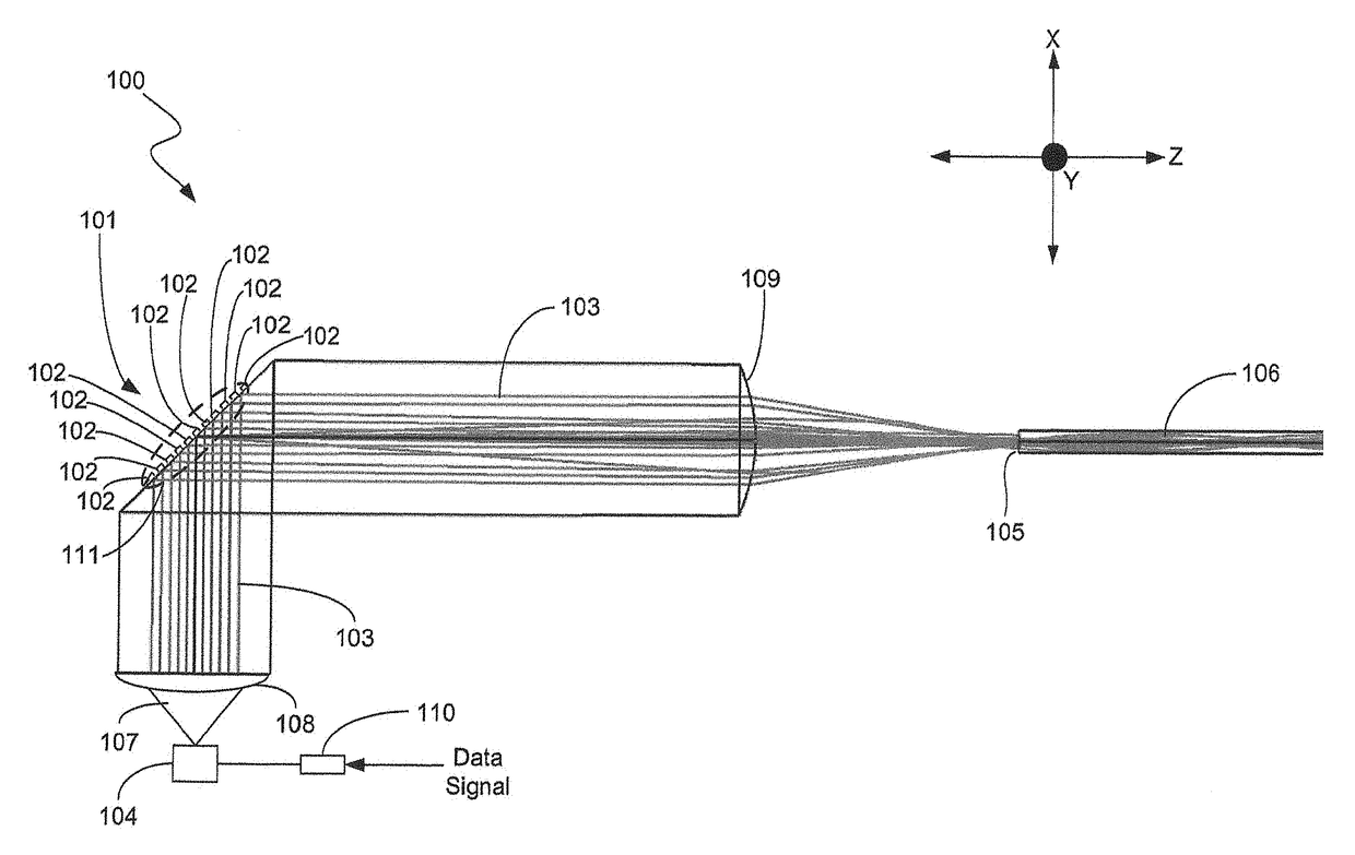
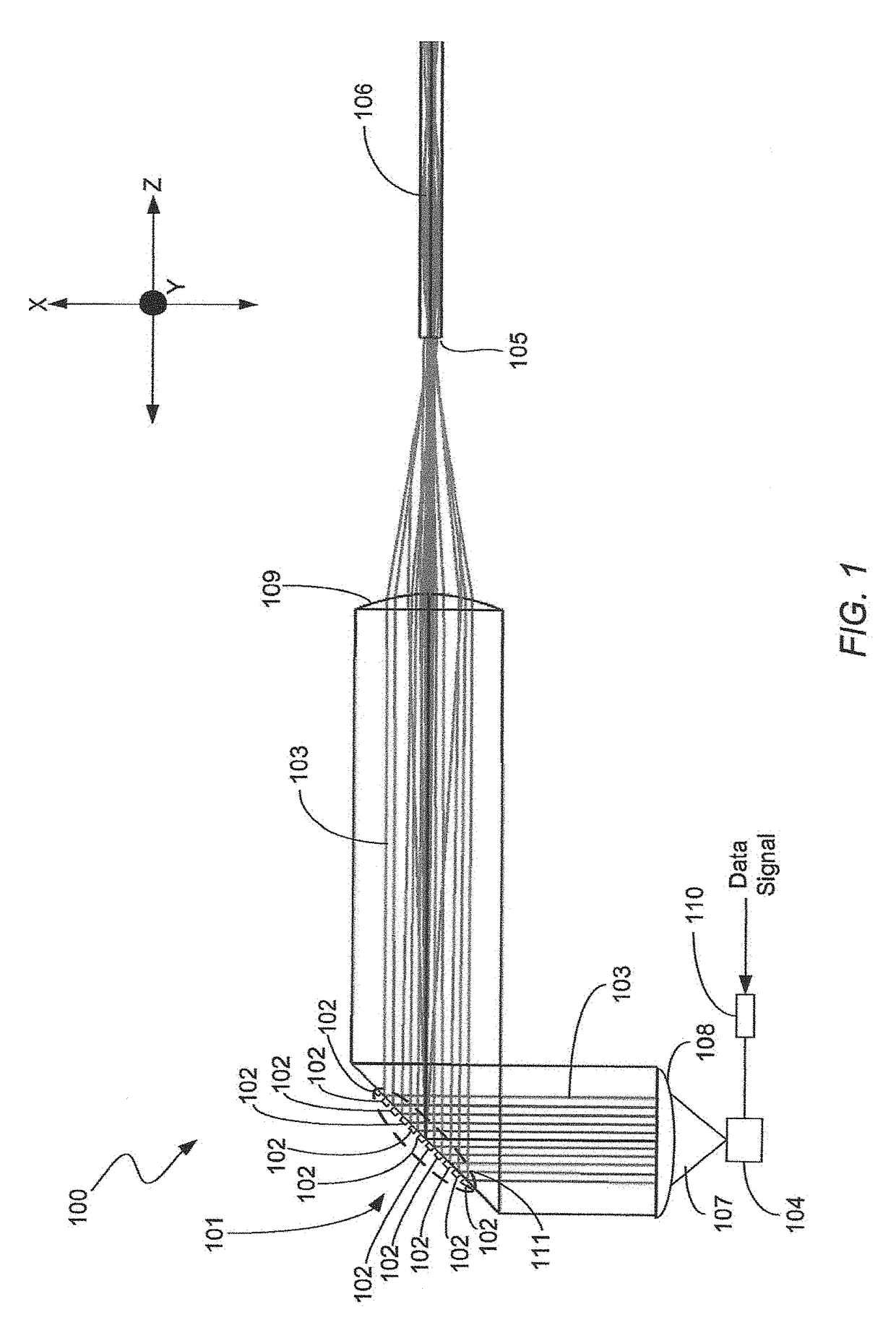
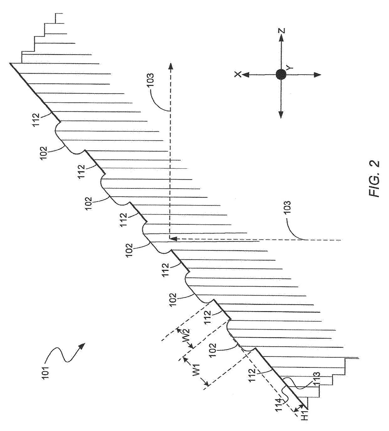
[0022]In accordance with the illustrative, or exemplary, embodiments described herein, an optical coupling system and method are provided for use in an optical communications module that improve forward optical coupling through better mode matching between the laser modes and the fiber modes and reduce back reflection into the laser. The optical coupling system has at least one flat surface having perturbations formed therein over at least a portion of the flat surface that intersects an optical pathway of the optical coupling system. The perturbations have a lateral width and a height that are preselected to improve forward optical coupling efficiency through better mode matching between the laser modes and the fiber modes and to decrease back reflection into the laser. The flat surface having the perturbations formed therein operates on the laser light beam in a predetermined manner to control the launch of the laser light beam onto the end face of the optical waveguide in a prede...


PUM


Abstract

An optical coupling system and method are provided for coupling light from a light source into an optical fiber that reduce back reflection of light into the light source and provide controlled launch conditions that improve forward optical coupling. The optical coupling system comprises at least one flat surface having perturbations formed therein over at least a portion of the flat surface that intersects an optical pathway. The perturbations have a lateral width and a height that are preselected to increase forward optical coupling efficiency and to decrease back reflection of the light beam from the optical fiber end face into the light source. The perturbations improve forward optical coupling by creating a complex light beam shape that is preselected to better match a spatial and angular distribution of a plurality of light modes of the optical fiber.

Description

TECHNICAL FIELD OF THE INVENTION[0001]The invention relates to optical communications modules and, more particularly, to an optical coupling system for use in an optical communications module that reduces back reflection of the light beam being launched into the end face of an optical waveguide while improving mode matching between the modes of the light beam and the modes of the optical waveguide.BACKGROUND OF THE INVENTION[0002]In optical communications networks, optical communications module (i.e., optical transceiver, transmitter and receiver modules) are used to transmit and receive optical signals over optical waveguides, which are typically optical fibers. An optical transceiver module includes a transmitter side and a receiver side. On the transmitter side, a laser light source generates a laser light beam and an optical coupling system receives the laser light beam and optically couples the laser light beam onto an end face of an optical fiber. The laser light source typica...

Claims


Application Information

Patent Timeline
Patent Type & Authority Patents(United States)
IPC IPC(8): G02B6/42G02B6/14
CPCG02B6/4207G02B6/14G02B6/4206G02B6/4255G02B6/4214G02B6/4296H04B10/25891
Inventor MOMTAHAN, OMID
Owner FOXCONN INTERCONNECT TECHNOLOGY LIMITED
Why Eureka
Try Eureka