Optical coupling

Inactive Publication Date: 2005-10-06
LOCKHEED MARTIN CORP
View PDF8 Cites 10 Cited by
  • Summary
  • Abstract
  • Description
  • Claims
  • Application Information

AI Technical Summary

Benefits of technology

[0010] Briefly, the present invention comprises an optical coupling apparatus and a method of optical coupling two optical fibers to each other where at least one of the optical fibers to be connected to another optical fiber is severed before the terminal end of the optical fiber to form two butt connectable severed ends in the severed optical fiber. One of the severed ends is mounted in one end of a rotationally member and the other severed end is mounted in the other end of a rotational member so that when the two rotational members are assembled into a rotational coupler the two severed ends of the severed optical fiber are in optical communication with each other though a rotateable butt connection. To reduce the back reflection between the butt connectable severed ends an optical conductive substance having an index of refraction matching the index of refraction of the optical fibers is placed between the two severed ends of the optical fiber. The severed ends of the optical fiber, which are in a butt connecting condition with respect to each other are thus in a condition to rotate with respect to one anther without a degradati

Problems solved by technology

One of the difficulties in optical coupling of the ends of optical fibers to each other is to avoid or reduce the back reflection at the junction between the ends of two optical fibers.
Unfortunately, in applications where an optical fiber has to be connected and disconnected the presence of a gel or liquid at the ends of the optical fibers not only hinders the connecting or disconnecting process but it is difficult to retain the optically conducting substance between the ends of the optical leads during the connection and disconnection process.
Therefore, a connection and disconnection process using a substance between the ends of the optical fibers, although reducing the back reflection, is ge

Method used


Image

  • Optical coupling
  • Optical coupling
  • Optical coupling

Examples


Example

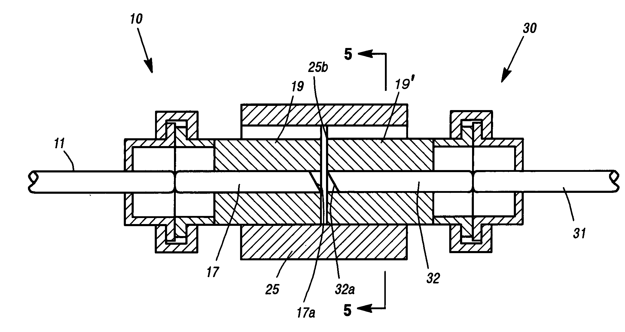
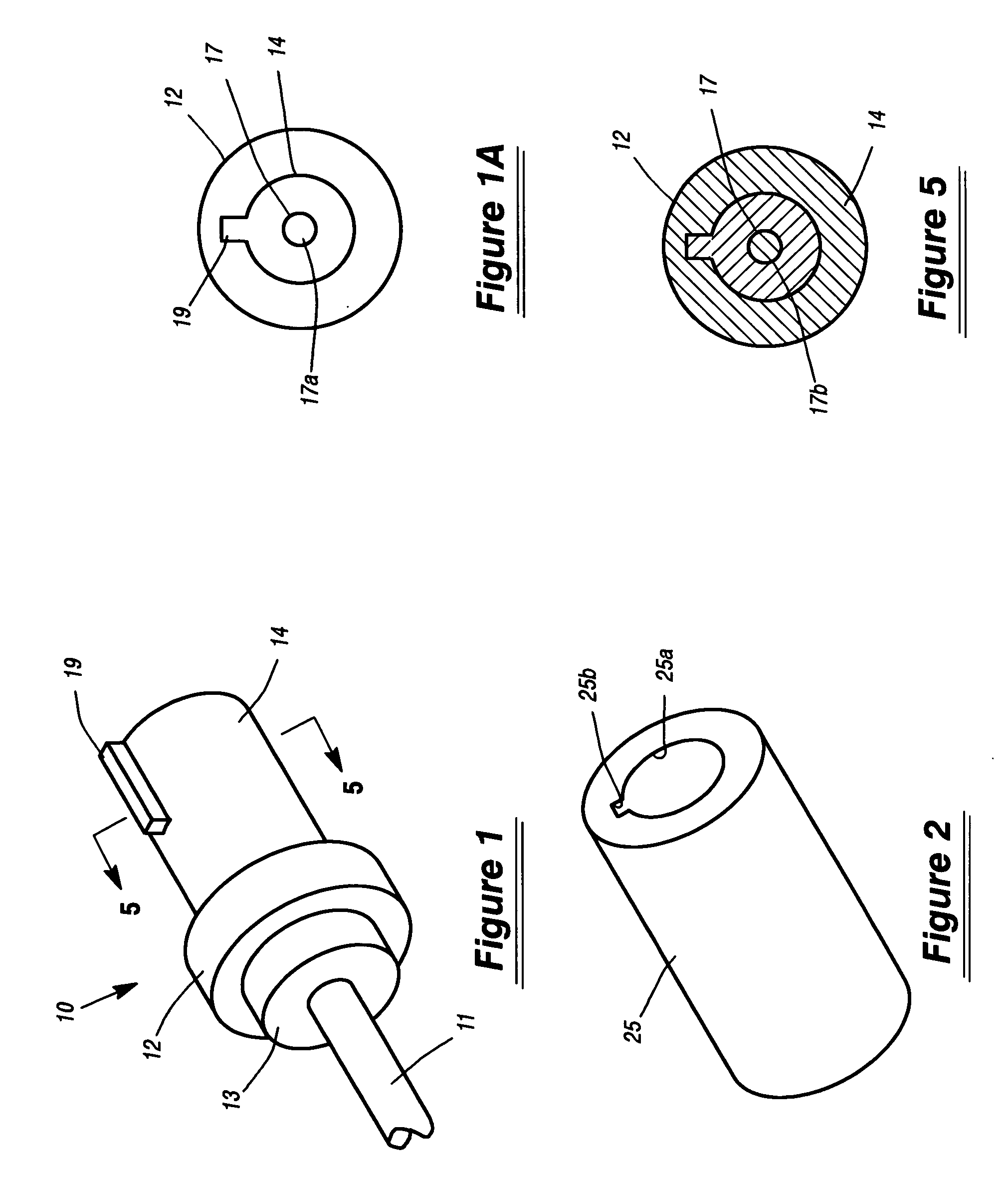
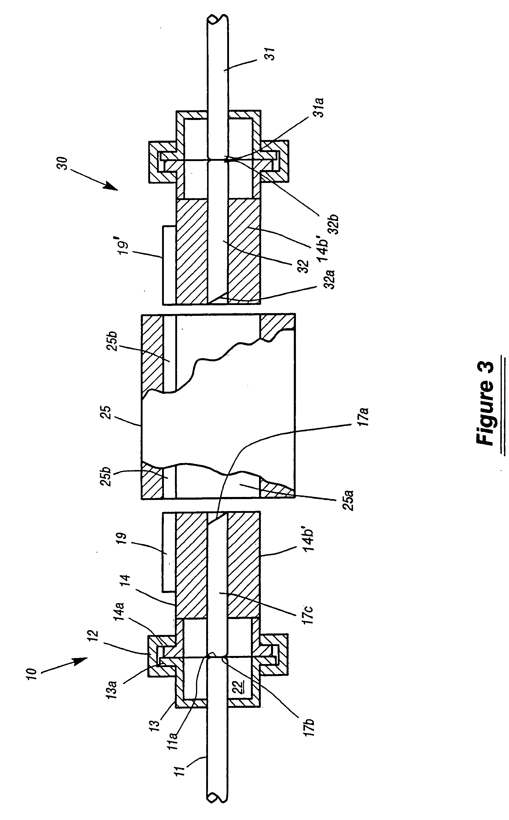
[0018] Referring to FIG. 1 and FIG. 3, reference numeral 10 identifies a three part rotatable coupling connector or rotateable coupler secured having one end secured to an optical lead or optical fiber 11. The rotatable coupler 10 includes a first flanged member 13 secured to the exterior surface of optical lead 11 and a second flanged member 14 located in a rotational relationship with respect to flanged member 13. Flanged members 13 and 14 are held in rotational engagement and alignment with each other by a U-shaped collar 12 that encompasses the flanges of members 13 and 14. A reference to FIG. 3 shows the flanges 13a and 14a of the flanged members 13 and 14 of coupling connector 10 held in rotational engagement by collar 12 to form a rotational joint.

[0019]FIG. 3 shows two identical rotateable couplers 10 and 30 in a condition for optically coupling optical fibers from two different sources. In the embodiment shown coupler 10 is shown in cross sectional view revealing flange 13...


PUM


Abstract

An apparatus and method for coupling and decoupling optical leads while preventing twists or kinks in the optical leas as well as back reflections with the apparatus including an a rotatable optical coupler and a non-rotatable optical coupler.

Description

FIELD OF THE INVENTION [0001] This invention relates generally to coupling and, more specifically, to coupling and decoupling optical leads to each other while minimizing reflections and twisting of the optical leads. CROSS REFERENCE TO RELATED APPLICATIONS [0002] None STATEMENT REGARDING FEDERALLY SPONSORED RESEARCH OR DEVELOPMENT [0003] None REFERENCE TO A MICROFICHE APPENDIX [0004] None BACKGROUND OF THE INVENTION [0005] One of the difficulties in optical coupling of the ends of optical fibers to each other is to avoid or reduce the back reflection at the junction between the ends of two optical fibers. [0006] One of the methods to optically couple two optical fibers, while minimizing back reflections, is to square or dome the ends of two optical fibers and abut the ends against each other and place a gel, or other optical conducting substance, which has an index of refraction that matches the index of refraction of the optical fibers, between the two ends of the optical fibers. ...

Claims


Application Information

Patent Timeline
IPC IPC(8): G02B6/36G02B6/38
CPCG02B6/3822G02B6/3851G02B6/3846
Inventor STEVENS, RICK C.
Owner LOCKHEED MARTIN CORP
Why Eureka
Try Eureka