Method of angle fusion splicing silica fiber with low-temperature non-silica fiber

Inactive Publication Date: 2005-03-15
NP PHOTONICS A CORP OF DELAWARE
View PDF13 Cites 10 Cited by
  • Summary
  • Abstract
  • Description
  • Claims
  • Application Information

AI Technical Summary

Benefits of technology

In view of the above problems, the present invention provides a low-cost approach for providing a low splice loss, low back reflection and mechanically robust angle fus

Problems solved by technology

This method avoids angle cleaving of a non-silica fiber and the alignment of

Method used


Image

  • Method of angle fusion splicing silica fiber with low-temperature non-silica fiber
  • Method of angle fusion splicing silica fiber with low-temperature non-silica fiber
  • Method of angle fusion splicing silica fiber with low-temperature non-silica fiber

Examples


Embodiment Construction

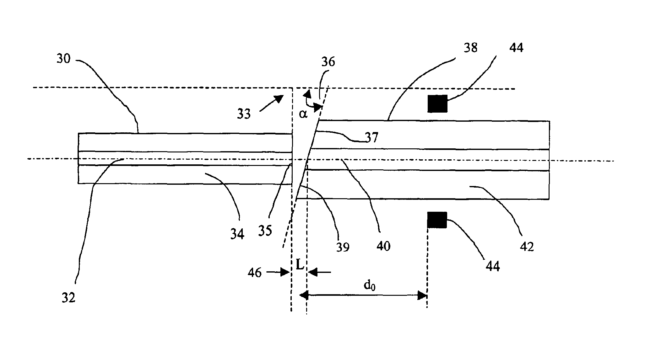
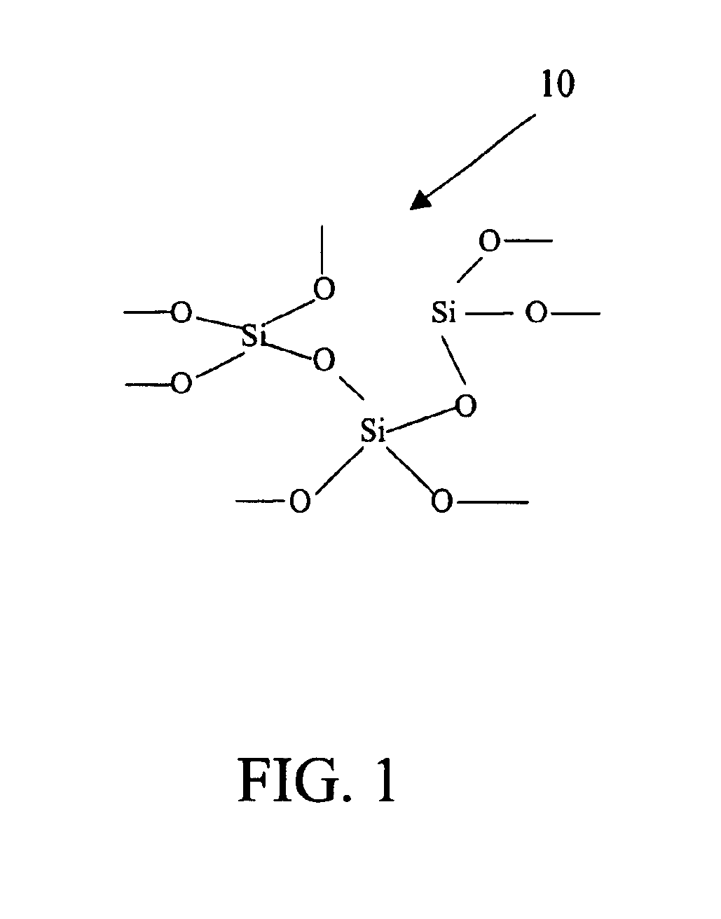
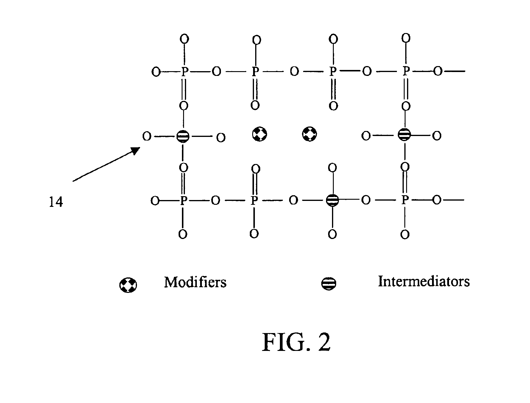
The present invention provides a low-cost approach for providing a low loss (<0.3 dB fusion splicing loss), low back reflection (<−50 dB or lower) and mechanically robust angle-fusion splice between a standard silica fiber and a specialty low-temperature non-silica glass fiber. This type of angle fusion splice is particularly useful in and was motivated by the development of a compact EDFA. To eliminate fiber management and reduce package size one must use a glass fiber that provides high gain per unit length. This in turn dictates a glass such as a multi-component phosphate glass that has a high solubility of rare-earth dopants such as erbium and ytterbium and exhibits the necessary spectroscopic properties.

Although the method of angle fusion splicing is generally applicable to any low-temperature non-silica glass fiber, the invention will now be described in the context of angle fusion splicing a low-temperature multi-component glass fiber to a standard silica fiber.

Low-...


PUM

PropertyMeasurementUnit
Fractionaaaaaaaaaa
Fractionaaaaaaaaaa
Fractionaaaaaaaaaa

Abstract

A low-cost approach is provided for forming a low splice loss, low back reflection loss and mechanically robust angle-fusion splice between a standard silica fiber and a low-temperature non-silica glass fiber. This is accomplished by angle cleaving the silica fiber, square cleaving the non-silica fiber and then asymmetrically heating the fibers to form an angle fusion splice. A matched angle at the end of the non-silica fiber is generated in situ during the splicing process. The tip of the angle-cleaved silica fiber may be polished flat back to the edge of the core to reduce the range of motion of the non-silica fiber during splicing thereby further reducing splice loss and enhancing the mechanical strength of the joint.

Description

BACKGROUND OF THE INVENTION1. Field of the InventionThe present invention relates to the field of fiber optics, and more specifically, to the angle fusion splicing of low-temperature non-silica fibers with silica glass fibers.2. Description of the Related ArtIn the field of fiber optics, joining or splicing of optical fibers is a well-known and widely practiced technique. The most common method for splicing of two standard fused silica fibers is based on the fusion of the adjacent ends of the optical fibers that are to be joined. The fibers are brought close to each other and are aligned so that their cores are coaxial with each other. Heat is transferred to both fiber ends by a filament around the fiber or an electric arc between two electrodes that are positioned on either side of the axis of the two optical fibers. This heat is sufficient to soften the glass at the end of each of the two fibers to be joined. The optical fibers are then brought in contact and the hardening of the ...

Claims


Application Information

Patent Timeline
IPC IPC(8): G02B6/255
CPCG02B6/2552G02B6/2551G02B6/03638
Inventor WANG, JIAFULI, WEIJIONG
Owner NP PHOTONICS A CORP OF DELAWARE
Why Eureka
Try Eureka