Rail anchor

a technology for rails and anchors, applied in the field of rail anchors, can solve problems such as special problems and damage to concrete anchors

Active Publication Date: 2011-01-13
PROGRESS RAIL SERVICES
View PDF11 Cites 3 Cited by
  • Summary
  • Abstract
  • Description
  • Claims
  • Application Information

AI Technical Summary

Benefits of technology

[0004]The present invention provides rail anchor particularly adapted for use in an application where the railroad rail is installed on concrete ties. The rail anchor is designed to protect the concrete tie from longit

Problems solved by technology

Special problems have arisen due to the use of concrete ties in certain railroad rail installations.
The particular problem with railroad rail mounted on concrete ties is longitudinal rail

Method used


Image

  • Rail anchor
  • Rail anchor
  • Rail anchor

Examples


Embodiment Construction

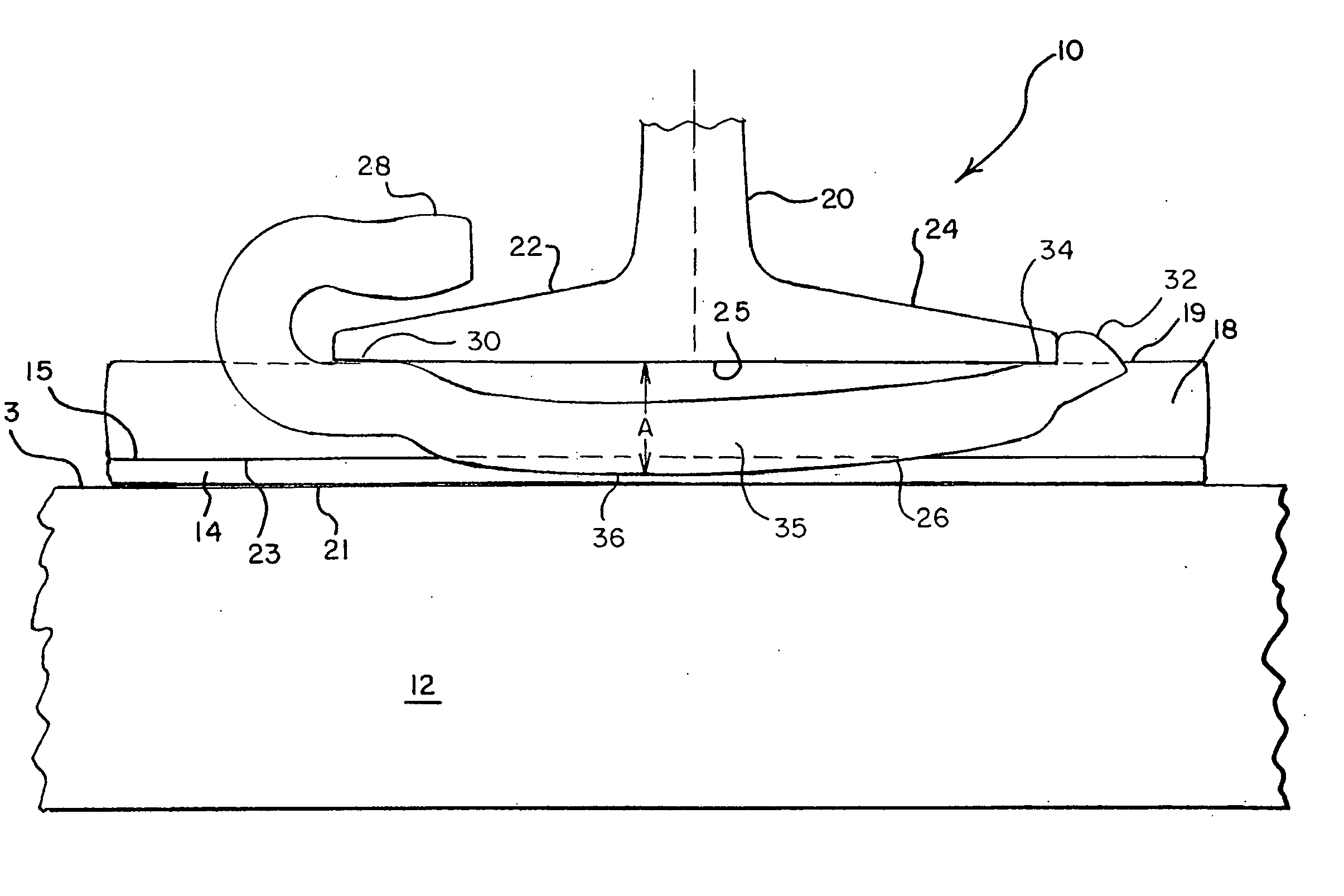
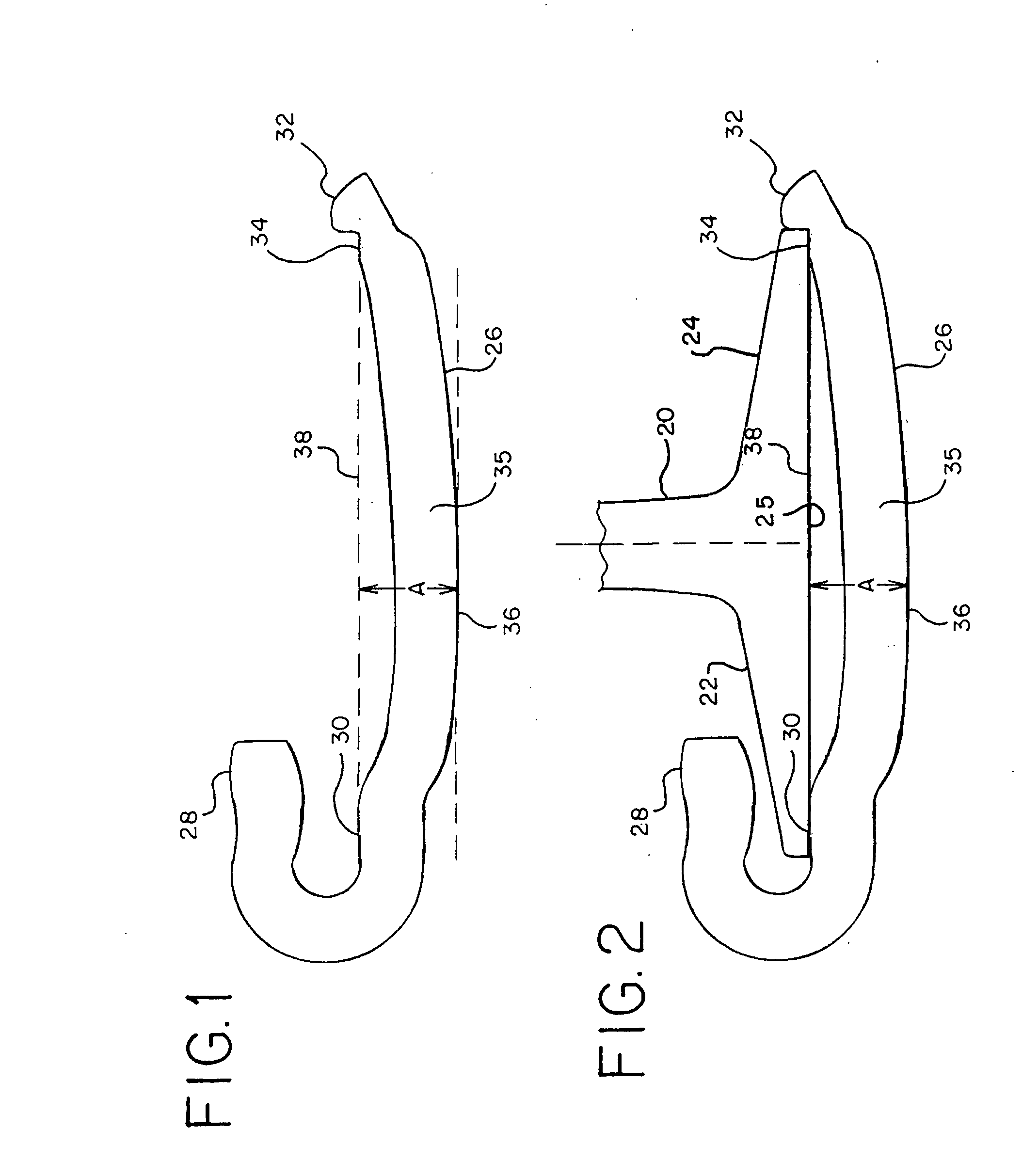
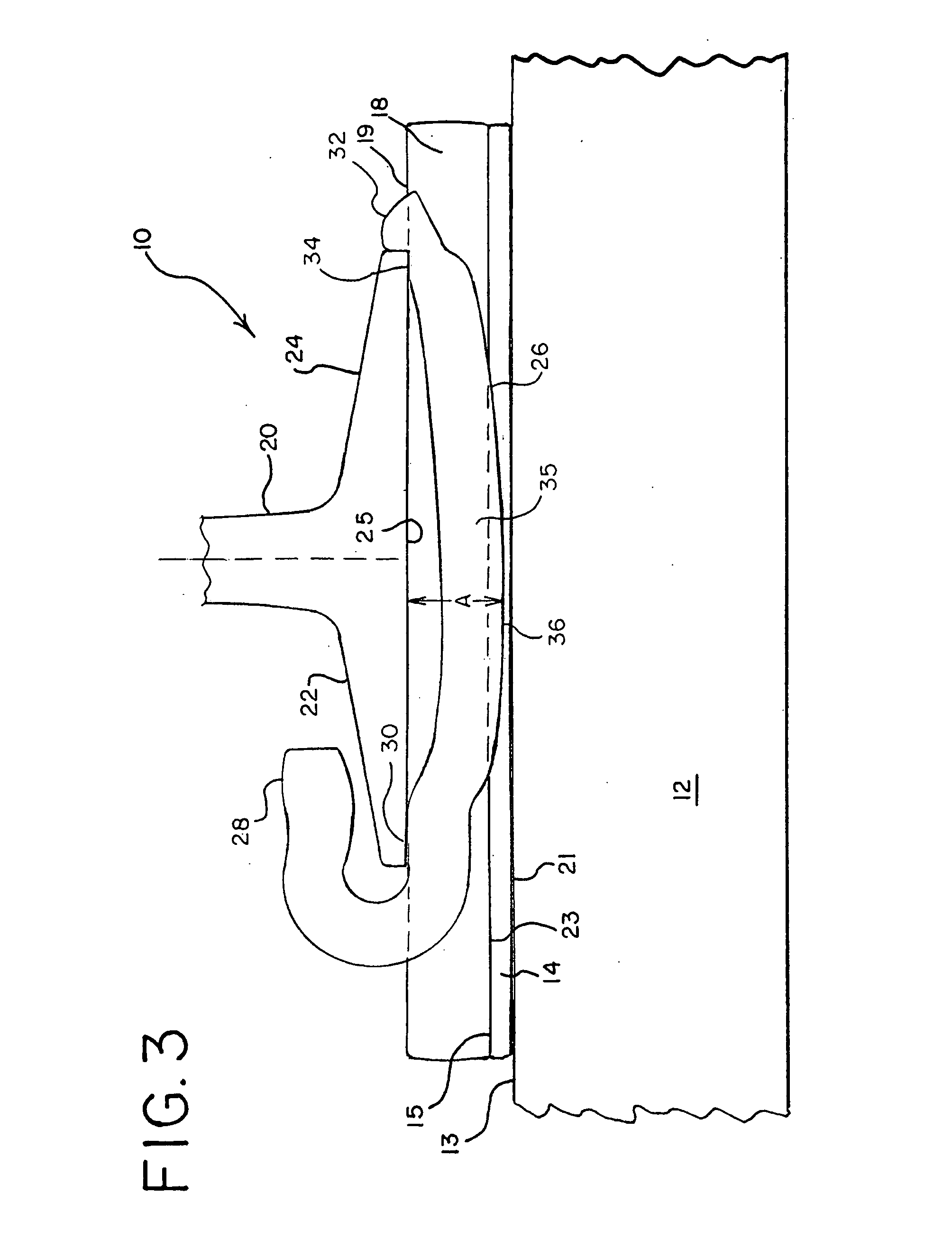
[0011]Referring now to FIG. 1, a rail anchor 26 in accordance with an embodiment of the present invention is shown in a side view. Rail anchor 26 is usually comprised of steel, and is a generally elongated shape with usually a square or rectangular cross section. Rail anchor 26 includes a first end 28 which is bent back at approximately 180° to form receiving opening 30. Rail anchor 26 also comprises second end 32 which is raised and which includes receiving indentation 34 on what can be deemed the top surface of rail anchor 26. The top facing surface of receiving opening 30 and the top facing surface of receiving indentation 34 define a plane 38 which is horizontal.

[0012]Rail anchor 26 also includes a center portion 35 which joins first end 28 with second end 32. Center portion 35 of rail anchor 26 includes a bottom surface 36 which extends downwardly from plane 38 a vertical distance A, which is typically between 0.875 inches and 1.00 inches (2.2 and 2.5 cm).

[0013]Referring now to...


PUM


Abstract

A rail anchor and a rail anchor assembly are provided for use with a concrete railroad tie. An elastomeric plate is placed on a top surface of the railroad tie. A rigid plate is placed on top of the elastomeric plate. The rail anchor is placed adjacent the elastomeric plate and the rigid plate. The rail anchor has a first end with a receiving opening and a second end with a receiving indentation to receive edges of the flanges of the railroad rail. The rail anchor has a center portion joining the two ends. The outer portion of the rail anchor extends downwardly an amount less than the thickness of the elastomeric plate and the rigid plate to avoid contact with the concrete railroad tie.

Description

BACKGROUND OF THE INVENTION[0001]In the installation and operation of railroad rail and the operation railroad engines and freight cars on such rail, the standard rail fastener is a spike driven into a wood tie on either side of the rail. Such arrangement is designed to keep the lateral spacing between rails to maintain gage distance. Tie plates are also utilized as bearing pads against lateral and vertical forces.[0002]Special problems have arisen due to the use of concrete ties in certain railroad rail installations. The particular problem with railroad rail mounted on concrete ties is longitudinal rail movement when holding is provided with resilient fasteners. Rail anchors can be used to restrict such longitudinal rail movement, which typically occurs during the acceleration and deceleration of trains or the expansion and contraction due to temperature change. However, abrasion from the steel rail anchor against the concrete tie sides tend to erode and eventually damage the conc...

Claims


Application Information

Patent Timeline
IPC IPC(8): E01B13/02E01B9/00
CPCE01B13/02
Inventor HENDERSON, JIMBOSSHAMMER, EDWALSH, CASEY
Owner PROGRESS RAIL SERVICES
Why Eureka
Try Eureka