Electronic connector assembly

a technology of electronic connectors and connectors, applied in the direction of electrical equipment, incorrect coupling prevention, coupling device connections, etc., can solve the problems of damage to the pins of the connectors, difficult to separate the two connectors,

Inactive Publication Date: 2011-01-27
HON HAI PRECISION IND CO LTD
View PDF8 Cites 4 Cited by
  • Summary
  • Abstract
  • Description
  • Claims
  • Application Information

AI Technical Summary

Problems solved by technology

It can be difficult to separate the two connectors if one or both of the connectors needs to be detached.
Typically, a user has to pry one of the connector back and forth to work it loose from the other which can damage pins of the connectors.

Method used


Image

  • Electronic connector assembly
  • Electronic connector assembly
  • Electronic connector assembly

Examples


Embodiment Construction

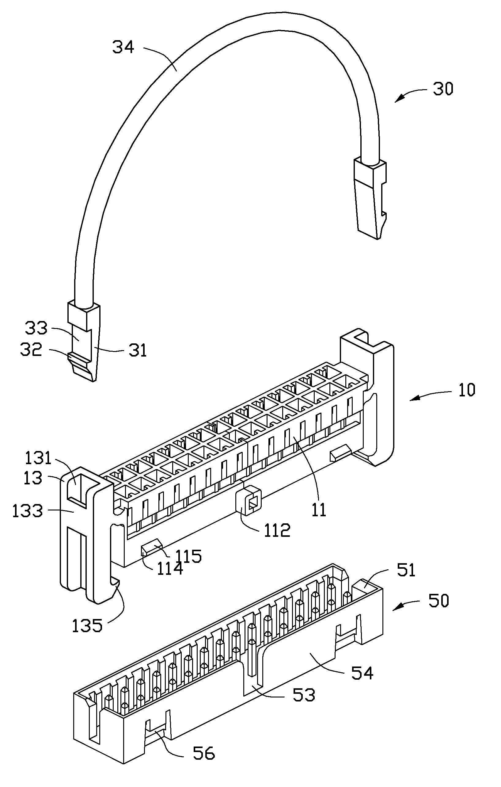
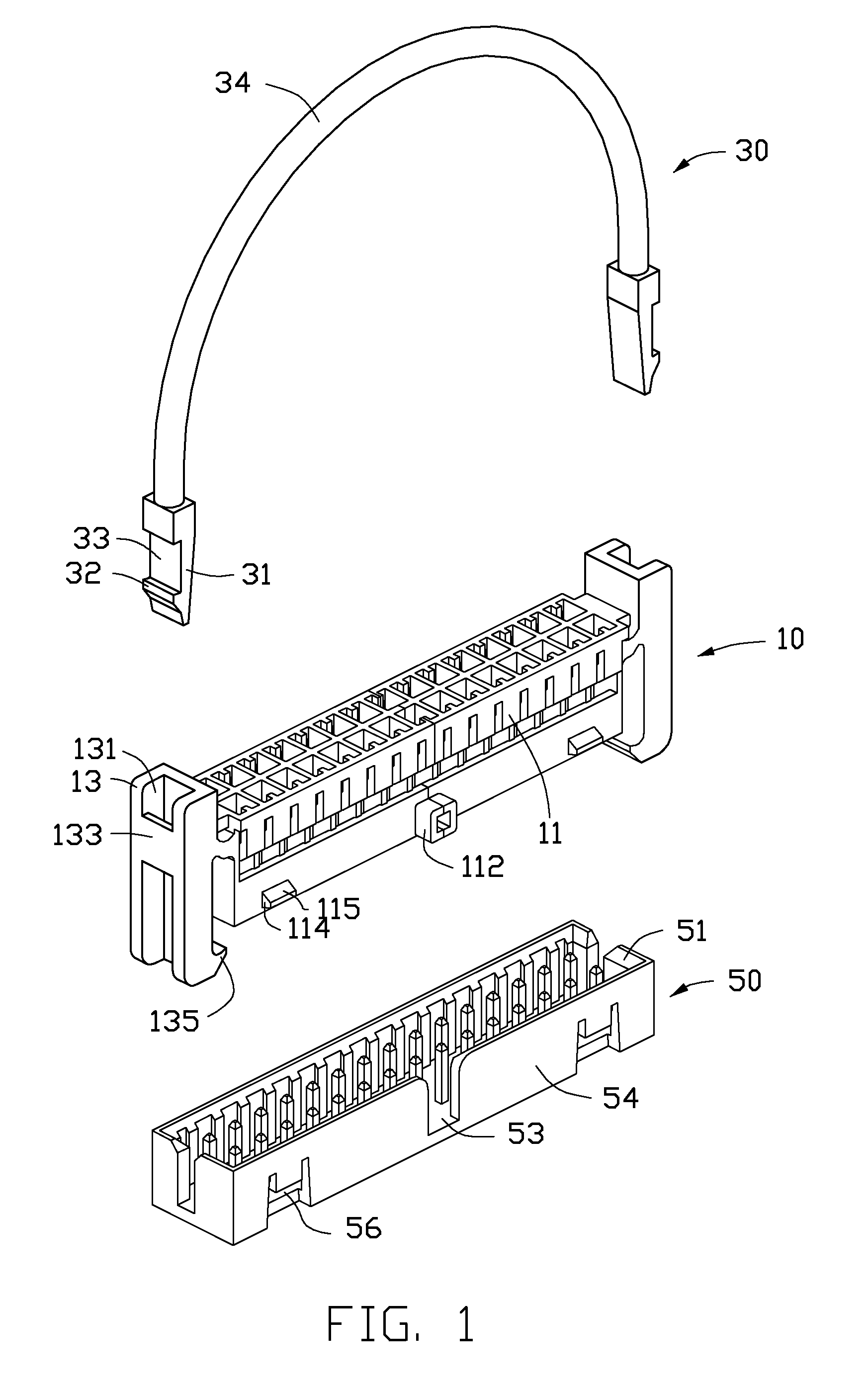
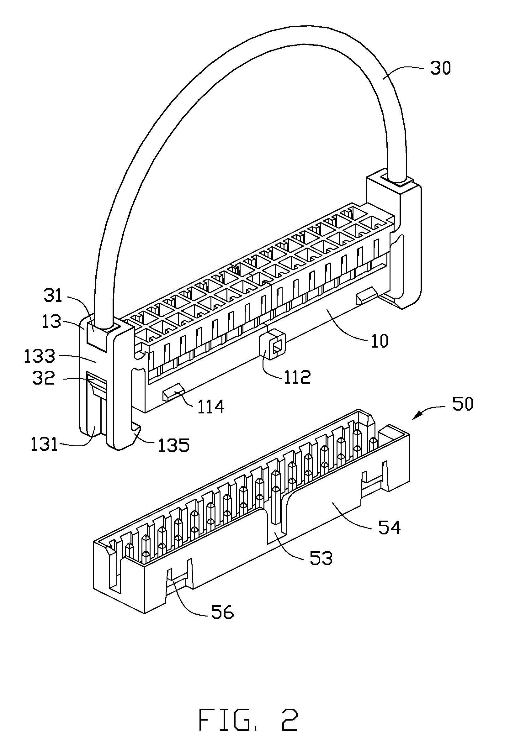
[0010]Referring to FIG. 1, an electronic connector assembly, in accordance with an embodiment, includes a first connector 10, a second connector 50, and a handle 30 adapted to be mounted on the first connector 10.

[0011]The first connector 10 includes a main portion 11 and two shoulder 13 formed on two sides of the main portion 11. A pair of flexible wedges 114 is formed on the main portion 11. A position block 112 is formed on the main portion 11, and located between the pair of wedges 114. A top surface and a bottom surface of each wedge 114 respectively form a slant surface 115 thereon. Each shoulder 13 defines a groove 131 extending in an up and down (vertical) direction. A retaining piece 133 bridges the groove 131. A hook 135 is formed on a bottom end of the shoulder 13.

[0012]The second connector 50 includes a frame 51, which includes an upright sidewall 54. The sidewall 54 defines a position slot 53 corresponding to the position block 112 of the first connector 10. A pair of s...


PUM


Abstract

An electronic connector assembly includes a first connector, a second connector, and a handle. The first connector includes a main portion and two shoulders. Each shoulder defines a groove. The main portion forms at least one wedge thereon. The second connector defines at least one securing hole, which receives the at least one wedge positioned therein. The handle includes a cord and two securing portions formed on opposite ends of the cord. The two securing portions are secured in the grooves of the two shoulders of the first connector to mount the handle on the first connector. The handle is capable of being pulled to disengage the first connector from the second connector.

Description

BACKGROUND[0001]1. Technical Field[0002]The present disclosure relates to electronic connectors, and particularly to a detachable electronic connector assembly.[0003]2. Description of Related Art[0004]Connectors are widely used to transmit signals between different electronic components. For transmitting signals between two electronic components, two connectors, tightly connected, are generally employed. It can be difficult to separate the two connectors if one or both of the connectors needs to be detached. Typically, a user has to pry one of the connector back and forth to work it loose from the other which can damage pins of the connectors.[0005]Therefore, there is room for improvement in the art.BRIEF DESCRIPTION OF THE DRAWINGS[0006]Many aspects of the embodiments can be better understood with references to the following drawings. The components in the drawings are not necessarily drawn to scale, the emphasis instead being placed upon clearly illustrating the principles of the ...

Claims


Application Information

Patent Timeline
Patent Type & Authority Applications(United States)
IPC IPC(8): H01R13/64
CPCH01R13/506H01R13/6335H01R13/6273
Inventor TSAI, LUNG-SHENGWU, CHIA-KANGCHEN, LI-PING
Owner HON HAI PRECISION IND CO LTD
Why Eureka
Try Eureka