Plug connection having a guide element optimized for preventing shavings

a technology of a guide element and a plug connection, which is applied in the direction of coupling device connection, final product manufacturing, sustainable manufacturing/processing, etc., can solve the problems of pin tin coating, pin contamination, pin damage, etc., and achieve the effect of preventing pin contamination, preventing pin damage, and preventing pin contamination

Active Publication Date: 2014-11-27
ROBERT BOSCH GMBH
View PDF10 Cites 9 Cited by
  • Summary
  • Abstract
  • Description
  • Claims
  • Application Information

AI Technical Summary

Benefits of technology

[0007]Thus, there is a need for an improved plug connector set-up and a corresponding manufacturing method for a plug connector set-up, which allow, in particular, damage to pins and, possibly, contamination of the contact elements, to be prevented.

Problems solved by technology

However, when the pins are led through the guide element, the pins, in particular, the tin coating of the pins, may be damaged.
In addition, the shavings formed may result in contamination of the contact elements.

Method used


Image

  • Plug connection having a guide element optimized for preventing shavings
  • Plug connection having a guide element optimized for preventing shavings
  • Plug connection having a guide element optimized for preventing shavings

Examples


Embodiment Construction

[0042]All of the figures are merely schematic representations of devices according to the present invention, and of their components according to exemplary embodiments of the present invention. In particular, distances and size relationships are not represented true to scale in the figures. In the various figures, corresponding elements are provided with the same reference numerals.

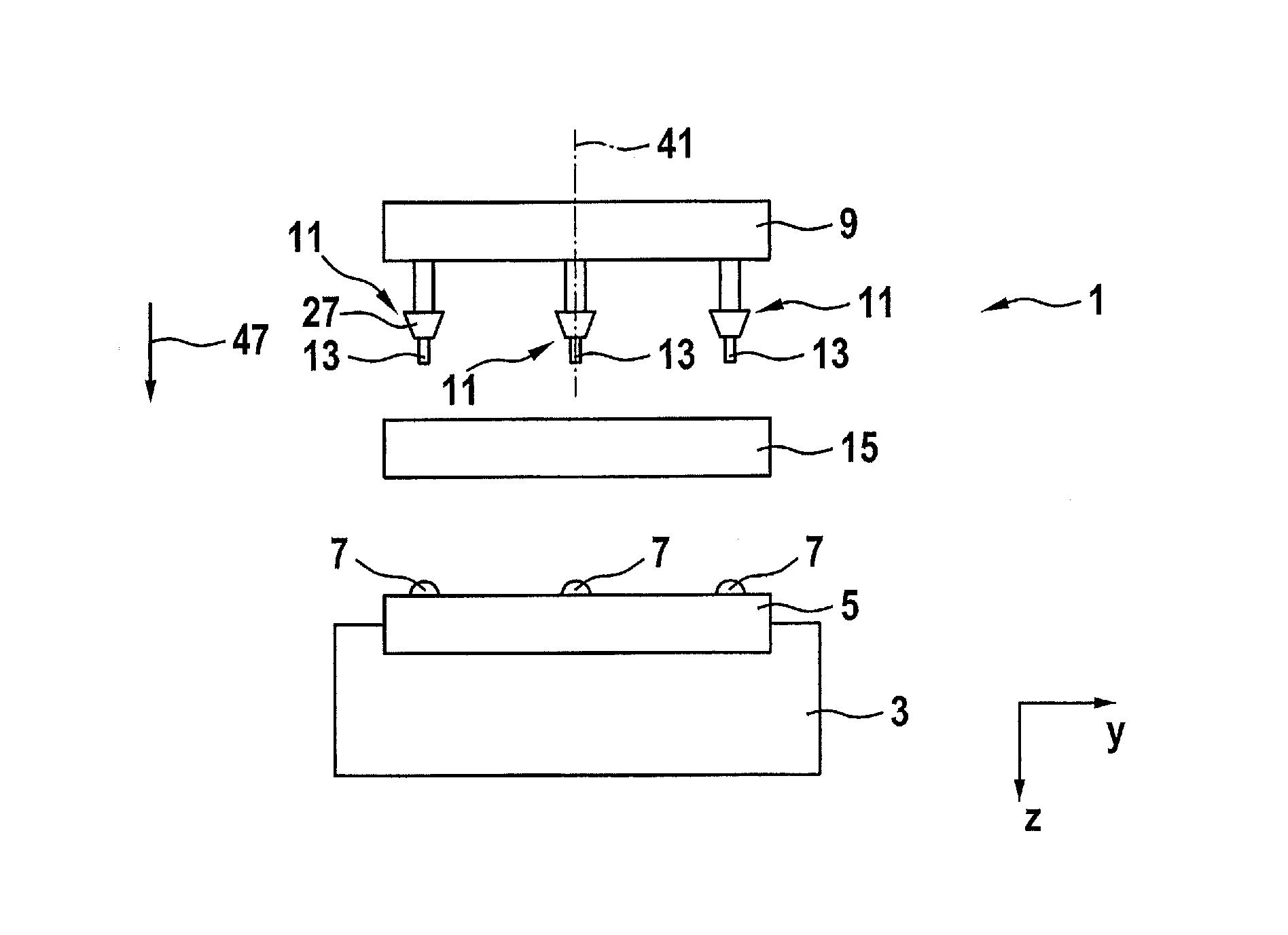
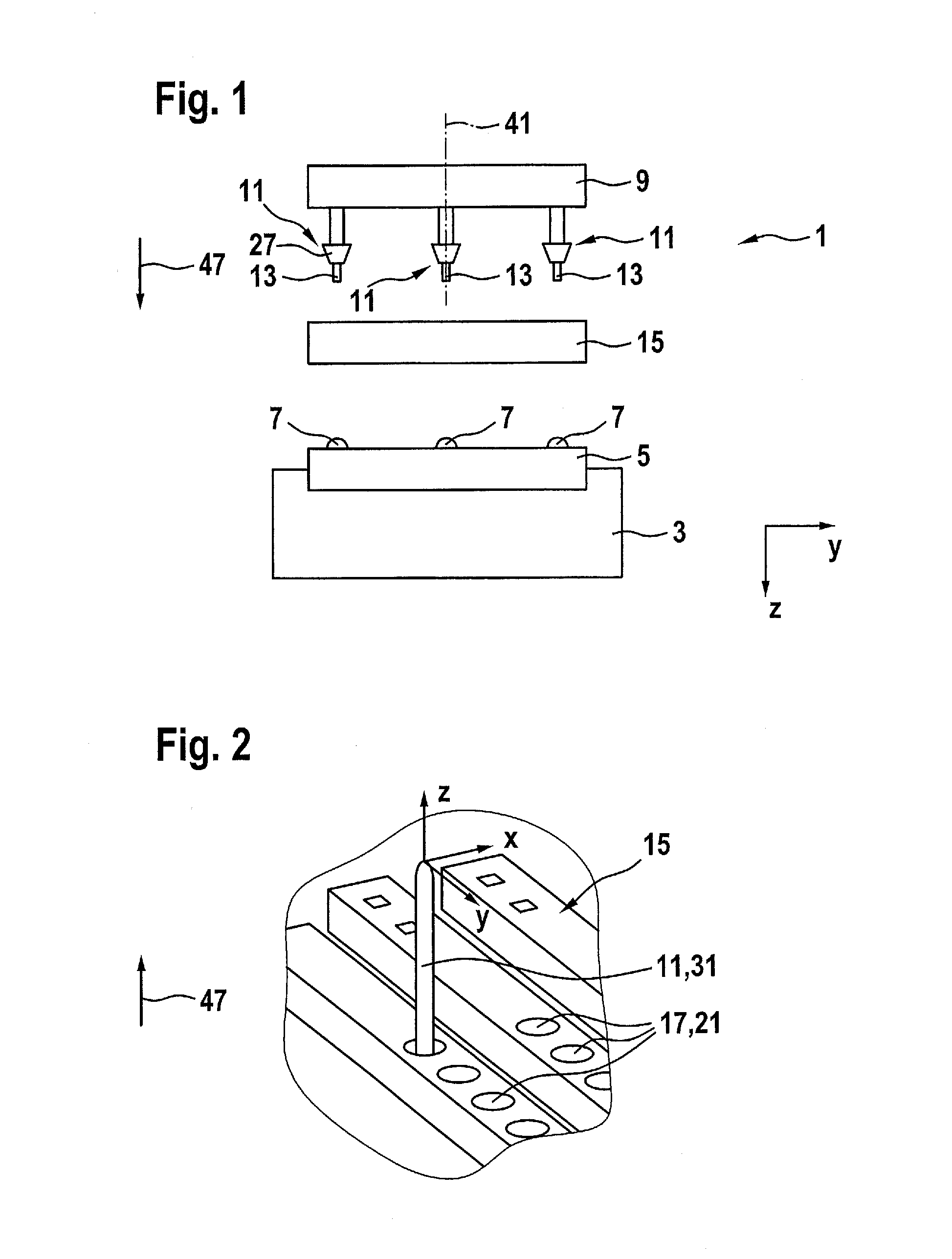
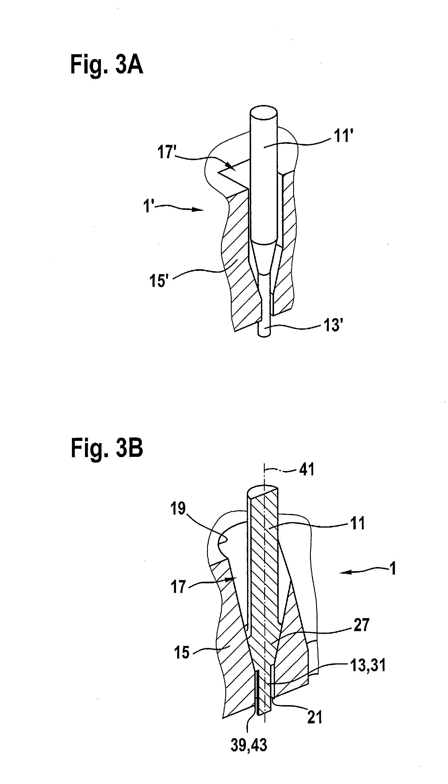
[0043]A highly schematic side view of a control unit having a plug connector set-up 1 is illustrated in FIG. 1. Control unit 3 includes a circuit board 5. Electrical contact elements in the form of soldering eyelets 7 are provided on circuit board 5. In order to produce an electrical connection between circuit board 5 and, for example, a pin support 9, which is provided with pins 11 and is on a wire harness, pins 11 are positioned on soldering eyelets 7. In order to ensure exact positioning of pins 11 on soldering eyelets 7, a guide element 15 in the form of a guideway is provided. As shown in FIGS. 2 thr...


PUM

PropertyMeasurementUnit
diameteraaaaaaaaaa
diameteraaaaaaaaaa
diameteraaaaaaaaaa

Abstract

A plug connector set-up for a control unit includes: a pin support having a pin; and a guide element having a lead-through for positioning the pin at a circuit board of the control unit. The lead-through has an entrance opening on the side facing the pin support and an outlet opening on the side facing away from the pin support. A diameter of the entrance opening is greater than a diameter of the outlet opening. The pin includes a centering region having a diameter which is less than the diameter of the entrance opening and greater than the diameter of the outlet opening.

Description

BACKGROUND OF THE INVENTION[0001]1. Field of the Invention[0002]The present invention relates to a plug connection having a guide a guide element.[0003]2. Description of the Related Art[0004]Motor vehicles may provide a multitude of safety, comfort and informational functions. To this end, different actuators and sensors may be positioned at or in the motor vehicles. A control unit provided in the motor vehicle may, for example, receive and process signals from the sensors and output control signals to the actuators. The more functions provided in a motor vehicle, the greater the demands may be on a control unit, which controls these functions. In particular, a number of electrical lines, which are used for exchanging data and signals between the control unit and sensors and actuators, increases.[0005]In order to allow, for example, assembly, maintenance or repair of the control unit, the lines are generally not rigidly connected to the control unit, but are releasably attached to t...

Claims


Application Information

Patent Timeline
Patent Type & Authority Applications(United States)
IPC IPC(8): H01R12/70H05K3/30
CPCH05K3/303H01R12/7005H01R12/75H01R13/41H01R13/631H05K2201/10318H05K2201/10424H05K2203/167Y02P70/50Y10T29/49147
Inventor LUDWIG, DIETERHEROLD, REINER
Owner ROBERT BOSCH GMBH
Why Eureka
Try Eureka