Self-take-up electronic sphygmomanometer

An electronic sphygmomanometer, wire-type technology, applied in the fields of vascular evaluation, medical science, diagnosis, etc., can solve the problems of inconvenience to carry, inconvenience to clean the display screen, and easy contamination of rubber tubes and cuffs. cleaning effect

Inactive Publication Date: 2022-05-27
SHENZHEN FINICARE CO LTD
View PDF0 Cites 1 Cited by
  • Summary
  • Abstract
  • Description
  • Claims
  • Application Information

AI Technical Summary

Problems solved by technology

[0004] The purpose of the present invention is to solve the problems in the prior art that the electronic sphygmomanometer is inconvenient to clean the display screen during use, and it is not convenient to automatically roll and store the rubber hose and cuff, which leads to the exposure of the rubber hose and cuff It is easy to be polluted and not easy to carry, so a self-retracting electronic sphygmomanometer is proposed

Method used


Image

  • Self-take-up electronic sphygmomanometer
  • Self-take-up electronic sphygmomanometer
  • Self-take-up electronic sphygmomanometer

Examples


Embodiment 1

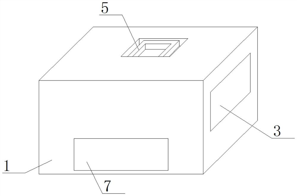
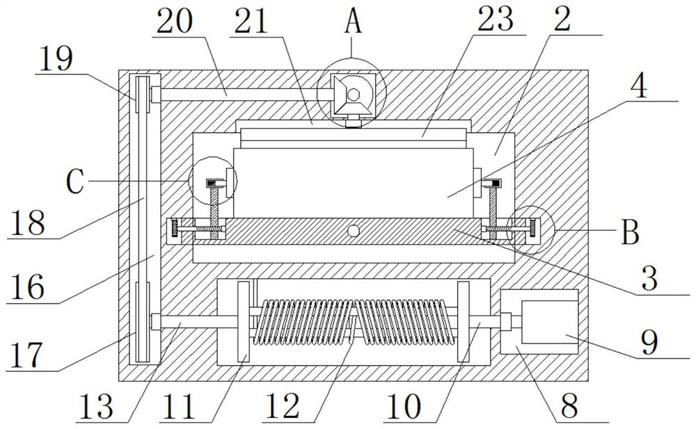
[0031] refer to Figure 1-7, a self-retracting electronic sphygmomanometer, comprising a casing 1, a first chute 2 is opened on one side of the casing 1, a bracket 3 is slidably installed in the first chute 2, and an electronic sphygmomanometer is placed in the bracket 3 The main body 4, the top of the casing 1 is provided with a first installation groove, the handle 5 is rotatably installed in the first installation groove, the wire take-up groove 6 is formed in the casing 1, the inspection port 7 is opened on one side of the casing 1, and the casing The body 1 is provided with a first empty slot 8 and a second empty slot 16, the inner walls of both sides of the wire take-up slot 6 are provided with a first rotation hole, and the two first rotation holes are respectively connected with the first empty slot 8 and the second empty slot. The grooves 16 communicate with each other, the first rotating shaft 10 and the second rotating shaft 13 are respectively rotatably installed i...

Embodiment 2

[0042] The difference from Embodiment 1 is that a first chute 2 is opened on one side of the housing 1 , a bracket 3 is slidably installed in the first chute 2 , the electronic sphygmomanometer body 4 is placed in the bracket 3 , and the housing 1 A first installation groove is opened on the top of the casing, a handle 5 is installed in the first installation groove, a wire take-up groove 6 is opened in the casing 1, an inspection port 7 is opened on one side of the casing 1, and a first installation is opened in the casing 1. There is an empty slot 8 and a second empty slot 16. The inner walls of both sides of the wire take-up slot 6 are provided with first rotation holes. The two first rotation holes are communicated with the first empty slot 8 and the second empty slot 16 respectively. The first rotating shaft 10 and the second rotating shaft 13 are respectively rotatably installed in the first rotating hole, a wire take-up mechanism is arranged in the wire take-up slot 6, a...


PUM


Abstract

The invention belongs to the field of electronic sphygmomanometers, particularly relates to a self-take-up type electronic sphygmomanometer, and aims to solve the problems that a display screen is inconvenient to clean and a rubber tube and a cuff are inconvenient to automatically take up and store in the using process of an existing electronic sphygmomanometer, so that the rubber tube and the cuff are exposed outside and are easy to pollute, and the existing electronic sphygmomanometer is inconvenient to carry. According to the scheme, the electronic sphygmomanometer comprises a shell, a first sliding groove is formed in one side of the shell, a support is installed in the first sliding groove in a sliding mode, an electronic sphygmomanometer body is placed in the support, a first installation groove is formed in the top of the shell, a handle is rotatably installed in the first installation groove, and a take-up groove is formed in the shell. The display screen can be conveniently cleaned, the rubber tube and the sleeve band can be conveniently and automatically rolled and stored, the rubber tube and the sleeve band can be prevented from being exposed outside and polluted, and the display screen is convenient to carry, simple in structure and convenient to use.

Description

technical field [0001] The invention relates to the technical field of electronic sphygmomanometers, in particular to a self-retracting electronic sphygmomanometer. Background technique [0002] Electronic sphygmomanometer is a medical device that uses modern electronic technology and the principle of indirect blood pressure measurement to measure blood pressure. Electronic sphygmomanometer is divided into arm type, wrist type and watch type; its technology has experienced the most primitive first generation (mechanical constant speed exhaust valve), second generation (electronic servo valve), third generation (pressurized synchronous measurement) and the development of the fourth generation (integrated gas circuit). Usually consists of an occlusion cuff, a sensor, an air pump, and a measurement circuit. Electronic devices for blood pressure measurement using oscillometric, offset, or similar non-invasive blood pressure indirect measurement principles. [0003] In the pri...

Claims


Application Information

Patent Timeline
Patent Type & Authority Applications(China)
IPC IPC(8): A61B5/021A61B5/022
CPCA61B5/022A61B5/02141A61B2560/0431
Inventor 李超
Owner SHENZHEN FINICARE CO LTD
Why Eureka
Try Eureka