
Eureka
For R&D, Eureka makes reading and utilizing patents & technical documents easy.
Eureka AIR
Designed for self-driven R&D workflows. Generate viable solutions, solve complex R&D challenges, empower your innovation with AI.

Eureka Materials
Designed for material experts only. Revolutionize your material R&D, from search, analyze, to developing new materials.

TechResearch
Generate reliable direction feasibility study reports for your R&D in just a few steps.

TechSeek
Discover and master advanced knowledge NOW. Basics, ideas, possibilities, all at once.

TechMind
As an expert in R&D Theories, TechMind can generates customized viable solutions instantly.

TechRisk
Analyze your overall solution with one click, know your potential R&D risks in advance.

TechMonitor
Get weekly tech updates, stay abreast of the latest tech innovations and key insights.
Esp for perforated sumps in horizontal well applications
- Summary
- Abstract
- Description
- Claims
- Application Information
AI Technical Summary
Benefits of technology
Problems solved by technology
Method used
Image

Examples
Embodiment Construction
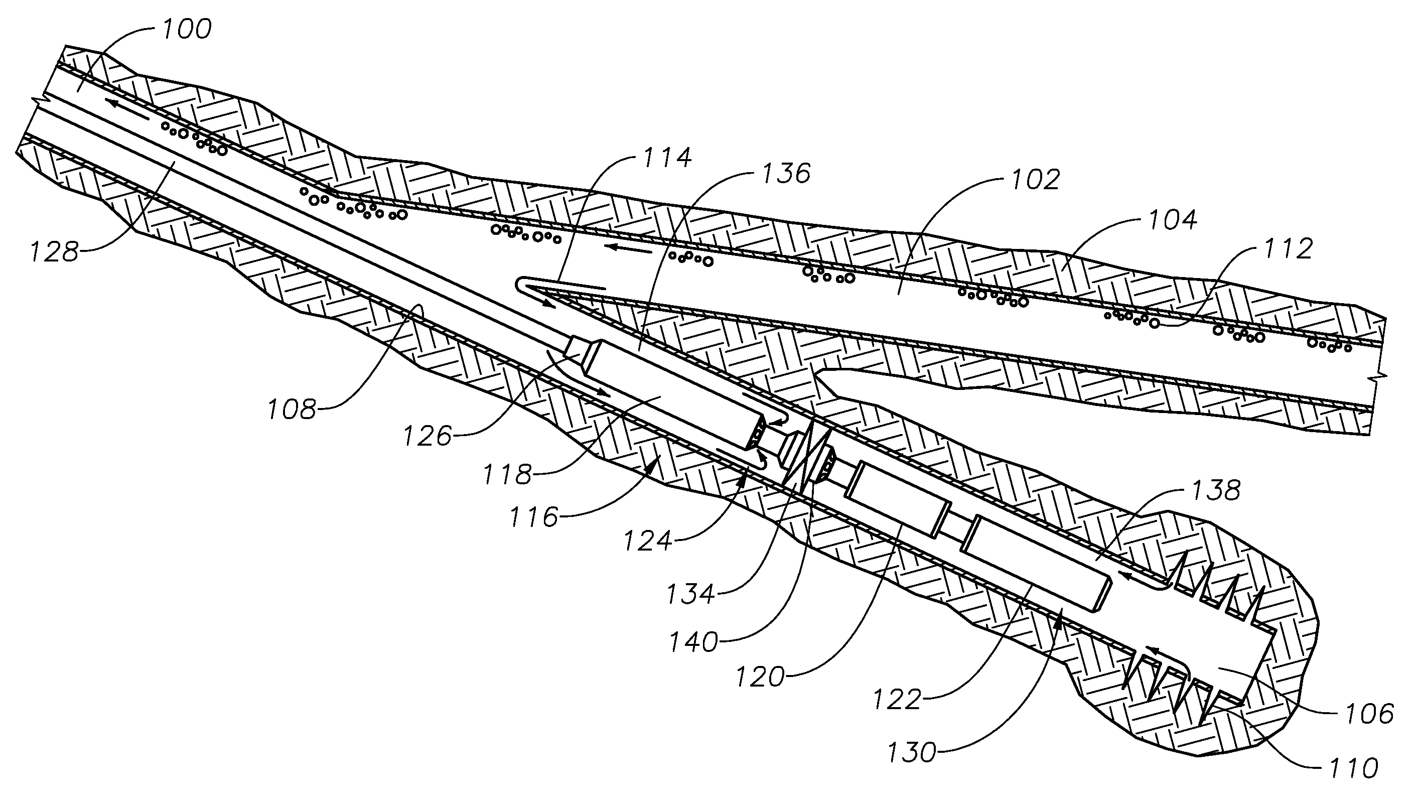
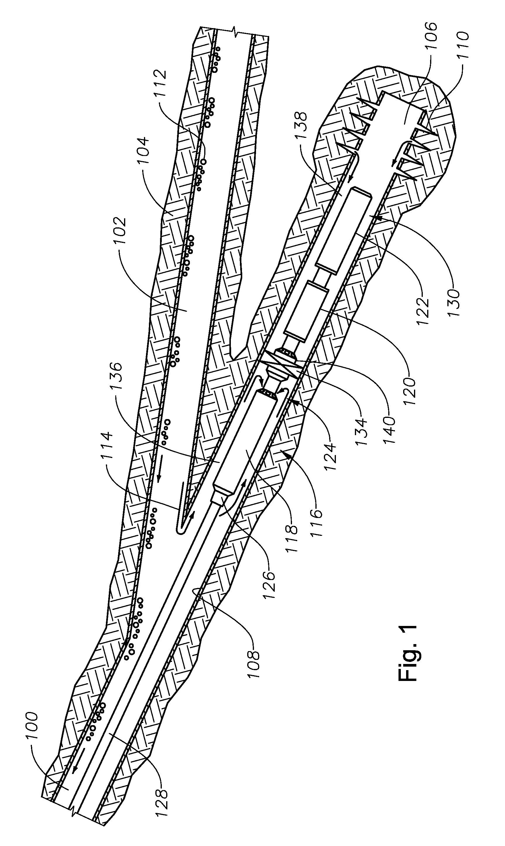
[0017]Referring to FIG. 1, wellbore 100, having horizontal branch 102, is drilled through subterranean formation 104. Sump 106 is drilled below horizontal branch 102 and generally has an orientation that is more vertical than horizontal branch 102. Sump 106 is generally defined as a low point below main wellbore 100 or horizontal wellbore 102. It is created by extending the descending wellbore 100 below the point where the descending wellbore 100 changes direction to a more horizontal orientation. Alternatively, sump 106 may be a descending branch below a horizontal section 102 of wellbore 100. The deepest part of sump 106 is generally deeper than the horizontal branch 102 associated with sump 106. In this example, sump 106 is co-axial with the upper portion of wellbore 106.
[0018]Casing 108 lines the wellbore of both horizontal branch 102 and sump 106. The casing in sump 106 may have perforations 110 to allow water to pass through casing 108 from rock formation 104 into sump 106. Ho...
PUM
 Abstract
Description
Claims
Application Information
 - R&D Engineer
- R&D Manager
- IP Professional
- Industry Leading Data Capabilities
- Powerful AI technology
- Patent DNA Extraction
Browse by: Latest US Patents, China's latest patents, Technical Efficacy Thesaurus, Application Domain, Technology Topic, Popular Technical Reports.
© 2024 PatSnap. All rights reserved.Legal|Privacy policy|Modern Slavery Act Transparency Statement|Sitemap|About US| Contact US: help@patsnap.com