Method for designing a light guide plate

a technology of light guide plate and light guide plate, which is applied in the direction of instruments, computing, electric digital data processing, etc., can solve the problems of reducing the uniformity of illumination of direct-type backlight module, consuming little power, and typically required backlight modul

Inactive Publication Date: 2011-02-24
TSINGHUA UNIV +1
View PDF0 Cites 5 Cited by
  • Summary
  • Abstract
  • Description
  • Claims
  • Application Information

AI Technical Summary

Problems solved by technology

Currently, liquid crystal displays (LCDs) are extensively used in a variety of electronic devices because they are thin, lightweight, long lasting, and consume little power.
However, backlight modules are typically required because liquid crystals are not self-lumin

Method used


Image

  • Method for designing a light guide plate
  • Method for designing a light guide plate
  • Method for designing a light guide plate

Examples


Embodiment Construction

The disclosure is illustrated by way of example and not by way of limitation in the figures of the accompanying drawings in which like references indicate similar elements. It should be noted that references to “an” or “one” embodiment in this disclosure are not necessarily to the same embodiment, and such references mean at least one.

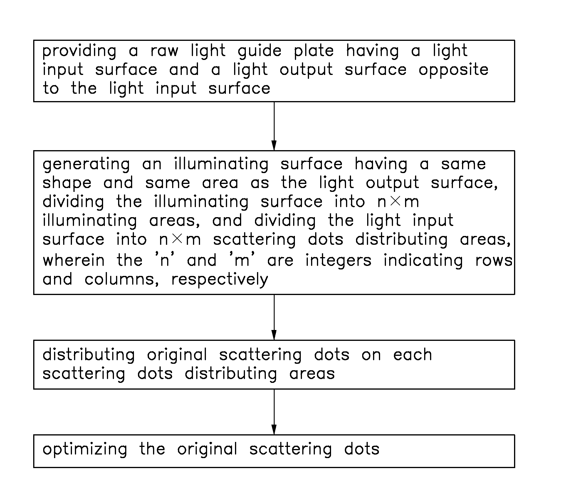
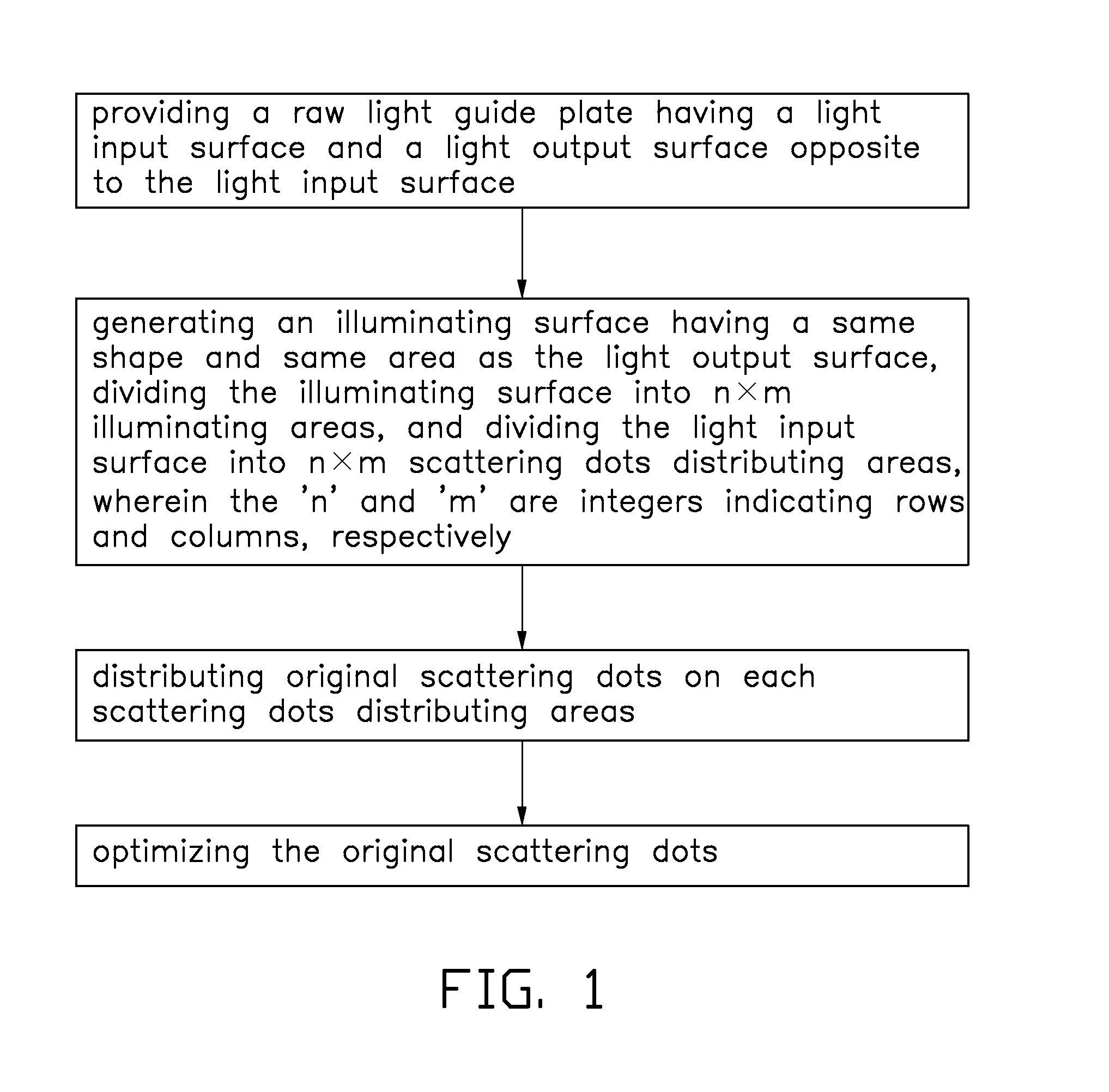
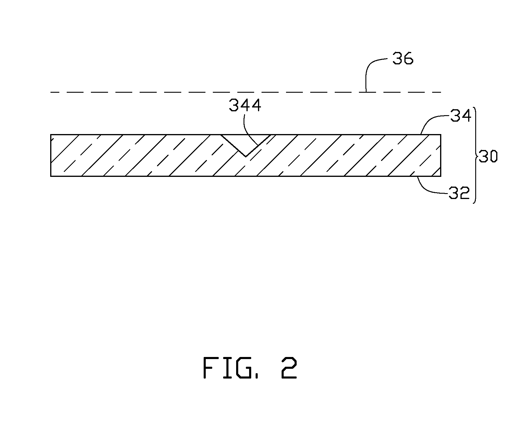
Referring to FIG. 1 to FIG. 3, a method for designing a light guide plate includes:

(a) providing a raw light guide plate 30 having a light input surface 32 and a light output surface 34 opposite to the light input surface 32;

(b) generating an illuminating surface 36 having a same shape and same area as the light output surface 34, dividing the illuminating surface 36 into n×m illuminating areas (not shown), and dividing the light input surface 32 into n×m scattering dots distributing areas 320, wherein the ‘n’ and ‘m’ are integers indicating rows and columns, respectively;

(c) distributing original scattering dots (not labeled) on each scattering dots d...


PUM


Abstract

The present disclosure relates to a method for designing a light guide plate. A raw light guide plate having a light input surface and light output surface opposite to the light input surface is provided. An illuminating surface having a shape and area same to that of the light output surface is built. The illuminating surface is divided into n×m illuminating areas, and the light input surface is divided into n×m scattering dots distributing areas corresponding to n×m illuminating areas. A number of original scattering dots are distributed on each scattering dots distributing areas. The original scattering dots are optimized.

Description

RELATED APPLICATIONSThis application claims all benefits accruing under 35 U.S.C. §119 from China Patent Application No. 200910189606.3, filed on Aug. 18, 2009 in the China Intellectual Property Office.BACKGROUND1. Technical FieldThe present disclosure relates to a method for designing a light guide plate.2. Description of Related ArtCurrently, liquid crystal displays (LCDs) are extensively used in a variety of electronic devices because they are thin, lightweight, long lasting, and consume little power. However, backlight modules are typically required because liquid crystals are not self-luminescent. Generally, backlight modules can be categorized as either direct-type backlight modules or edge-type backlight modules according to the placement of the light sources. The direct-type backlight modules are more widely employed in numerous applications because direct-type backlight modules can provide high illumination in comparison with edge-type backlight modules.A light guide plate ...

Claims


Application Information

Patent Timeline
IPC IPC(8): G06F17/50
CPCG02B6/0036G02B6/0065G02B6/0061G02B6/0043
Inventor ZHANG, HEZHU, JUNZHAO, YANJIN, GUO-FAN
Owner TSINGHUA UNIV
Why Eureka
Try Eureka