Method for designing a light guide plate and method for manufacturing the same

a technology of light guide plate and manufacturing method, which is applied in the direction of lighting and heating apparatus, instruments, mechanical equipment, etc., can solve the problems of reducing the uniformity of illumination of direct-type backlight module, and typically required backlight modul

Active Publication Date: 2012-11-06
TSINGHUA UNIV +1
View PDF10 Cites 1 Cited by
  • Summary
  • Abstract
  • Description
  • Claims
  • Application Information

AI Technical Summary

Benefits of technology

[0005]A light guide plate is a core component in a backlight module, the main function of which is to convert a linear light source or a point light source into a planar light source with good illuminance uniformity. A light guide plate for a direct-type backlight module according to a related art includes a top surface, a light input surface opposite to the top surface, and at least one side connecting the light input surface and the top surface. At least one of the light input surface and the top surface includes a plurality of scattering dots. The distribution of the scattering dots on a corresponding surface of the light guide plate remarkably affects the illuminance uniformity and efficiency of the light guide plate. However, in the related art, the distribution of the scattering dots on the surface of the light guide plate does not provide uniform light output from the light guide plate, thereby reducing the uniformity of illumination of the direct-type backlight module.

Problems solved by technology

However, backlight modules are typically required because liquid crystals are not self-luminescent.
However, in the related art, the distribution of the scattering dots on the surface of the light guide plate does not provide uniform light output from the light guide plate, thereby reducing the uniformity of illumination of the direct-type backlight module.

Method used


Image

  • Method for designing a light guide plate and method for manufacturing the same
  • Method for designing a light guide plate and method for manufacturing the same
  • Method for designing a light guide plate and method for manufacturing the same

Examples


Embodiment Construction

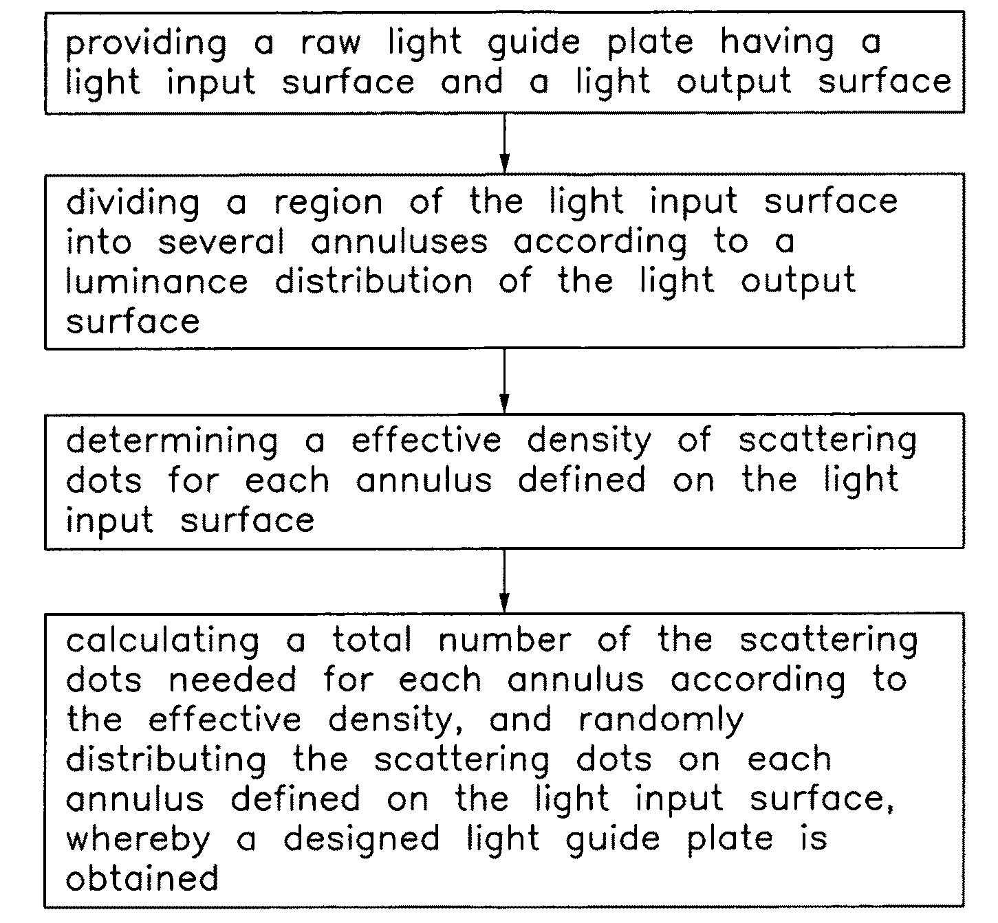
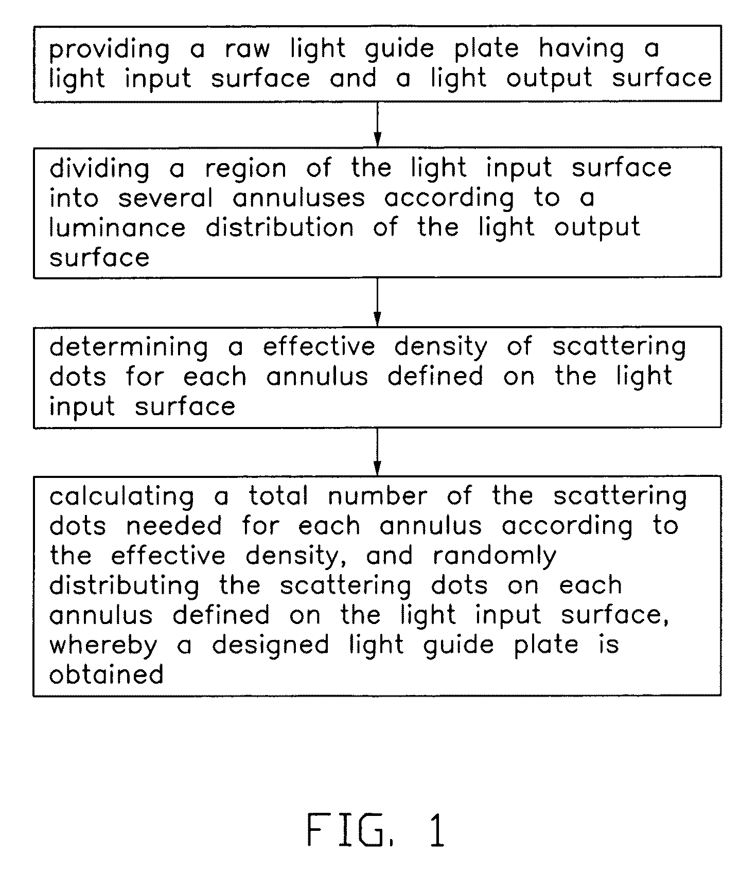
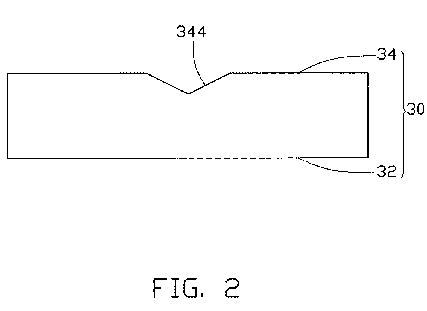
[0014]Referring to FIG. 1 and FIG. 2, a method for designing a light guide plate includes:[0015](a) providing a raw light guide plate 30 as shown in FIG. 2, the raw light guide plate 30 has a light input surface 32 and a light output surface 34 substantially parallel to the light input surface 32;[0016](b) dividing the region of the light input surface 32 into several concentric annuluses according to an illuminance distribution E(ρ,θ), shown in FIG. 3, of the light output surface 34 by determining radii of concentric circles used to form the annuluses, where ρ is the polar radius; and θ is the polar angle;[0017](c) determining a most effective density D(ρ,θ) for scattering dots 320 for each annulus defined on the light input surface 32; and[0018](d) calculating a total number N of the scattering dots 320 needed for each annulus according to effective density, and randomly distributing the scattering dots 320 on each annulus achieving design of a new light guide plate 30a as shown i...


PUM


Abstract

A method for designing a light guide plate includes the following steps. A raw light guide plate having a light input surface and a light output surface is provided. A region of the light input surface is divided into several annuluses according to a luminance distribution E(ρ,θ) of the light output surface. A scattering dots density D(ρ,θ) of each annulus on the light input surface is figured out. A total number N of the scattering dots of each annulus on the light input surface are gained, and the scattering dots is randomly distributed in the each annulus defined on the light input surface, whereby a designed light guide plate is obtained.

Description

BACKGROUND[0001]1. Technical Field[0002]The present disclosure relates to a method for designing a light guide plate and a method for manufacturing the same.[0003]2. Description of Related Art[0004]Currently, because liquid crystal displays (LCDs) are thin, lightweight, long lasting and consume little power, they are extensively used in a variety of electronic devices. However, backlight modules are typically required because liquid crystals are not self-luminescent. Generally, backlight modules can be categorized as either direct-type backlight modules or edge-type backlight modules according to the placement of the light sources. The direct-type backlight modules are more widely employed in numerous applications because direct-type backlight modules can provide high illumination in comparison with edge-type backlight modules.[0005]A light guide plate is a core component in a backlight module, the main function of which is to convert a linear light source or a point light source in...

Claims


Application Information

Patent Timeline
Patent Type & Authority Patents(United States)
IPC IPC(8): G06F19/00F21S2/00F21V8/00G02B6/00
CPCG02B6/0043G02B6/0065G02B27/0012
Inventor ZHAO, YANZHU, JUNZHANG, HEJIN, GUO-FAN
Owner TSINGHUA UNIV
Why Eureka
Try Eureka