Manifold and system for servicing multiple wells

Inactive Publication Date: 2011-03-03
ISOLATION EQUIP SERVICES
View PDF3 Cites 51 Cited by
  • Summary
  • Abstract
  • Description
  • Claims
  • Application Information

AI Technical Summary

Benefits of technology

[0010]Embodiments of the present invention are directed to an apparatus, system and method of selectively servicing two or more wells concurrently. A fluid, such as a fracturing fluid is pumped from pumping units through a manifold that is fluidly connected to the two or more wells. The velocity of the fluid is reduc

Problems solved by technology

The reduction of the velocity of the fluid reduces the erosive effects of the fl

Method used


Image

  • Manifold and system for servicing multiple wells
  • Manifold and system for servicing multiple wells
  • Manifold and system for servicing multiple wells

Examples


Embodiment Construction

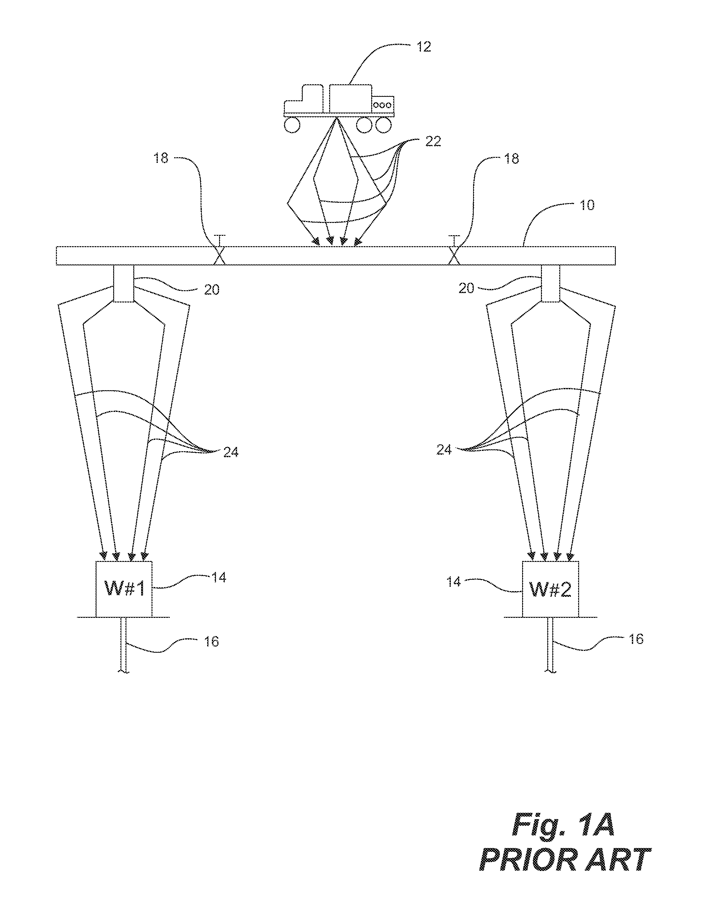
[0033]As shown in FIG. 1A, in a prior art multi-well stimulation operation, a prior art manifold 10 is utilized for fluidly connecting one or more stimulation fluid sources 12, typically pumpers, to a wellhead 14 of each of a plurality of wells 16 so as to permit selectively accessing two or more of the wells 16 concurrently. The prior art manifold 10 comprises a plurality of large, full-bore sized inline gate valves 18 therein for isolating selected wells 16. The manifold 10 receives the stimulation fluid from the one or more pumpers 12 at high velocity for selective delivery through large outlets 20, maintaining the high velocity of the fluid delivered therefrom, to the selected wells 16. Applicant notes that when one or more of the gate valves 20 are closed for isolating any of the wells 16 from the manifold 10, any wells 16 fluidly connected downstream from the closed gate valve 18 are isolated. Thus, selection of wells 16 to be serviced is not flexible. Further, it has been not...


PUM

PropertyMeasurementUnit
Fractionaaaaaaaaaa
Timeaaaaaaaaaa
Flow rateaaaaaaaaaa

Abstract

A manifold for distribution of well servicing fluids, such as fracturing fluids, to a plurality of wells. The manifold has a single bore through which the fluid flows and a plurality of outlets which are connected to the bore. Two or more of the outlets deliver the fluid to each wellhead. Valves are positioned in each of the outlets so that each of the wellheads can be independently isolated from the fluids for selecting which of the wells will be serviced at any given time. A total cross-sectional area of the outlets feeding each of the wells is greater than the cross-sectional area of the bore which results in a velocity reduction in the outlets which reduces erosion in the manifold and the downstream components Systems are described using prior art manifolds or manifolds according to embodiments of the invention for use specifically with fracturing fluids containing proppant. Proppant can be delivered to the fracturing fluid through the manifold, directly to the wellhead or both, to reduce erosion. Use of a manifold according to embodiments of the invention, in combination with the systems described, are particularly useful for reducing erosion with proppant-laden fracturing fluids.

Description

FIELD OF THE INVENTION[0001]Embodiments of the invention relate to servicing multiple wells with a fluid and, more particularly, to manifolds and valving therein for selectively accessing the wells and further to minimize the erosive effects of stimulation fluids therein.BACKGROUND OF THE INVENTION[0002]There are an increasing number of subterranean hydrocarbon reservoirs which are accessed using multiple wells for optimizing production therefrom. The wells and wellheads connected thereto are often closely spaced, the wellbores being angled downwardly and radially outwardly to access as much as the reservoir as possible.[0003]Many or all of multiple pay zones in such reservoirs may be characterized by low permeability or other characteristics which require stimulation of one or more of the wells for increasing production therefrom. During selective stimulation of the wells, which may include fracturing operations performed on one well, wireline operations may be also be performed on...

Claims


Application Information

Patent Timeline
IPC IPC(8): E21B19/00B23P17/00
CPCY10T29/4973E21B21/062
Inventor CHEREWYK, BORIS (BRUCE) P.JOHNSON, JERRY
Owner ISOLATION EQUIP SERVICES
Why Eureka
Try Eureka