Direct metal laser sintered flow control element

Active Publication Date: 2009-07-23
CONTROL COMPONENTS INC
View PDF19 Cites 79 Cited by
  • Summary
  • Abstract
  • Description
  • Claims
  • Application Information

AI Technical Summary

Benefits of technology

[0016]The above-mentioned deficiencies and needs associated with flow control elements of the prior art are specifically addressed and alleviated by various aspects of the invention as disclosed herein. More particularly, in one aspect, the invention includes a flow control element formed by direct metal laser sintering wherein a variety of complex flow passages can be formed in the flow control element. For example, the flow passages can be formed along at least two axes that may each be oriented orthogonally (i.e., p

Problems solved by technology

Furthermore, it should also be noted that the flow control element is not limited to cylindrical fl

Method used


Image

  • Direct metal laser sintered flow control element
  • Direct metal laser sintered flow control element
  • Direct metal laser sintered flow control element

Examples


Example

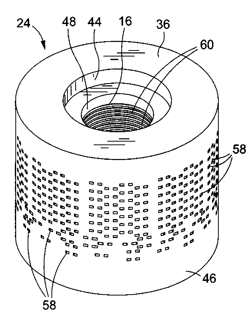
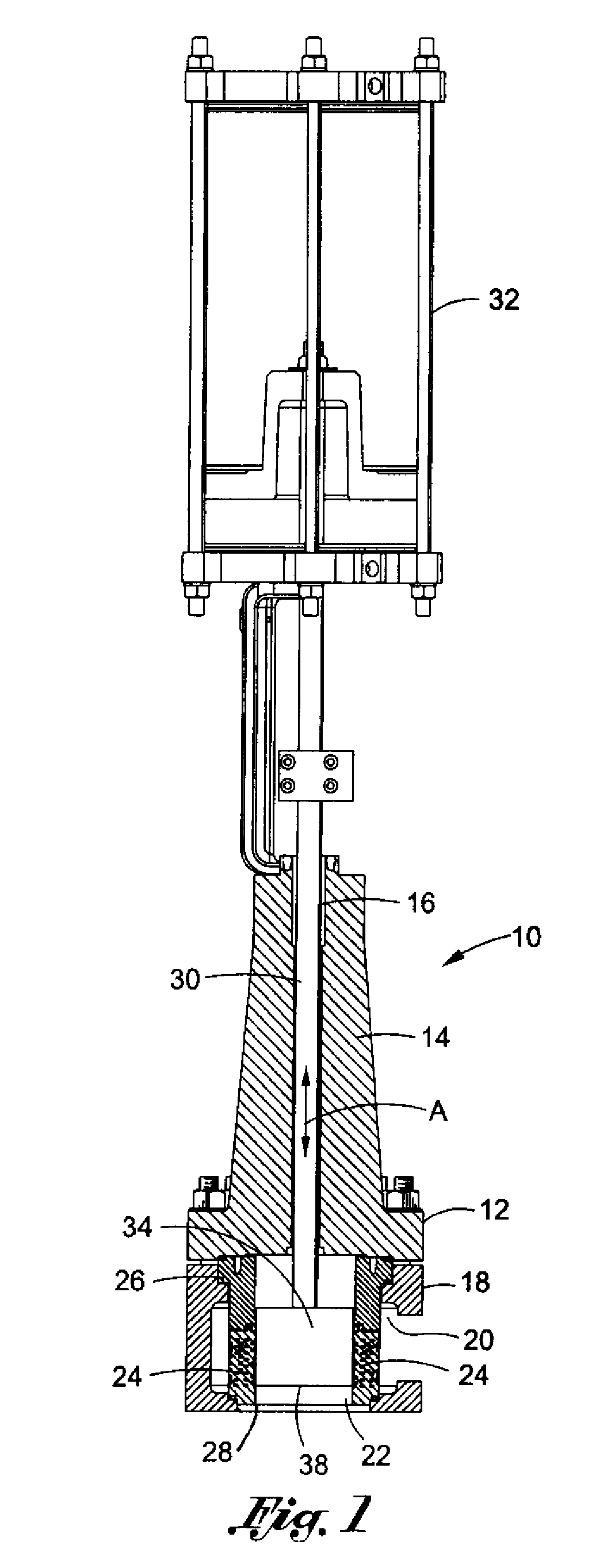
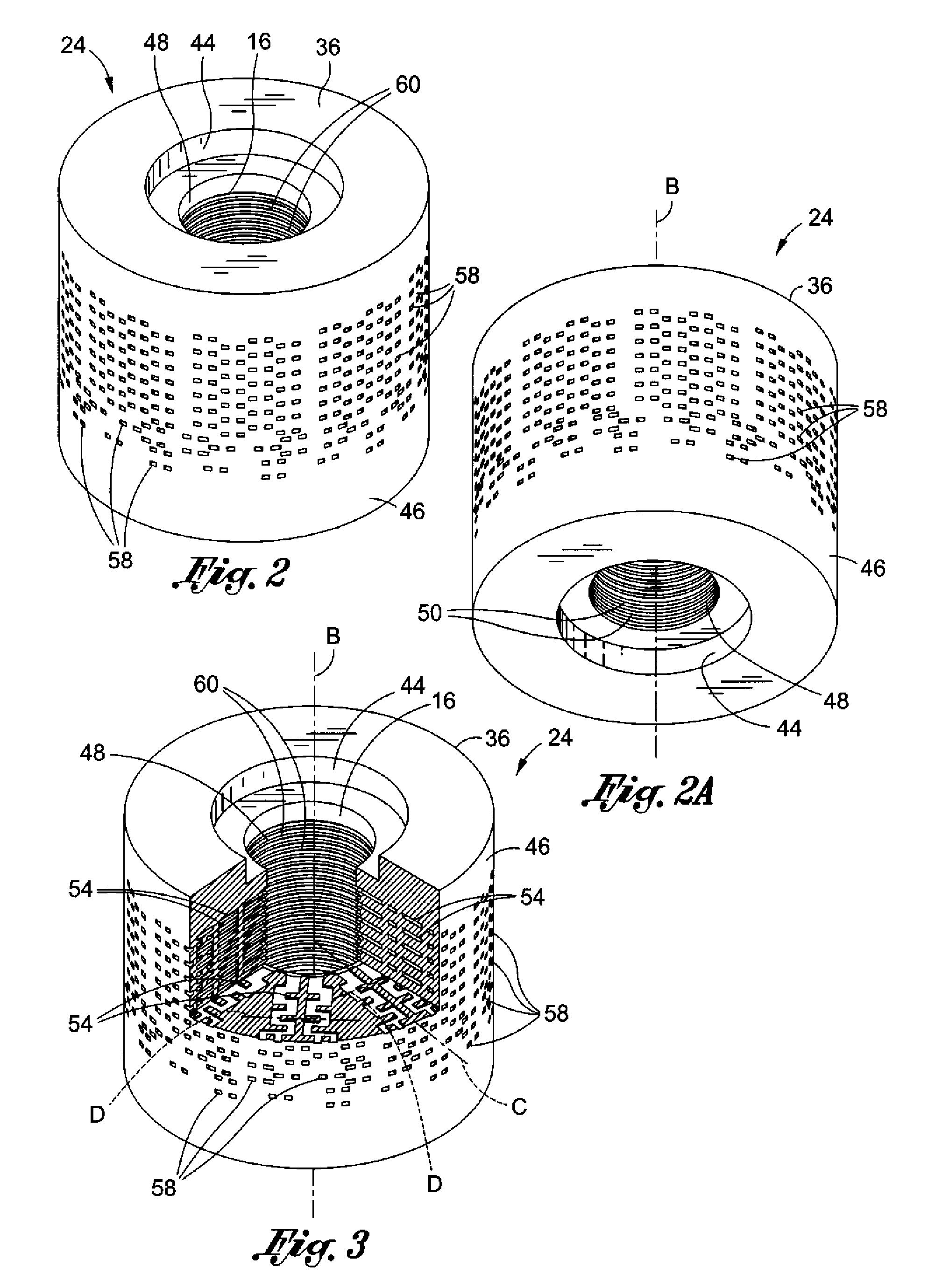
[0036]Referring now to the drawings wherein the showings are for purposes of illustrating preferred embodiments of the present invention and not for purposes of limiting the same, FIG. 1 illustrates a valve assembly 10 within which a flow control element 24 may be employed. As will be explained in greater detail below, the flow control element 24 may be formed using direct metal laser sintering of successive layers of powdered material. As distinguished from green state technology wherein the powdered material may be pre-formed into its final shape prior to sintering and unitizing the green state disk stack as described above, the direct metal laser sintering process uses raw powdered material. Laser energy is successively applied to the successively applied layers of raw powdered material in correspondence to a computer model of the flow control element 24. The computer model and, hence, the finished flow control element 24 is formed with a plurality of tortuous flow passages 54 fo...


PUM

PropertyMeasurementUnit
Angleaaaaaaaaaa
Flow rateaaaaaaaaaa
Widthaaaaaaaaaa

Abstract

A flow control element comprises a cylindrical element body having a bore formed therethrough. The cylindrical element body may include inner and outer peripheral surfaces and define a plurality of tortuous flow passages which extend between the inner and outer peripheral surfaces. The flow control element is formed as a unitary structure wherein the flow passages are oriented along at least two axes. The flow control may be formed by direct to metal laser sintering wherein successive layers of powdered metallic material are solidified by applying laser energy to the selected portions until the flow element is formed as a unitary structure with a plurality of flow passages extending therethrough. The laser energy is selectively applied to the powdered metallic material according to a computer model of the flow control element.

Description

CROSS-REFERENCE TO RELATED APPLICATIONS[0001](Not Applicable)STATEMENT RE: FEDERALLY SPONSORED RESEARCH / DEVELOPMENT[0002](Not Applicable)BACKGROUND OF THE INVENTION[0003]The present invention relates generally to fluid control and, more particularly, to a throttling device or flow control element adapted for reducing the velocity of fluid flowing therethrough and which may be economically mass produced with a plurality of multi-axis internal flow passages. The flow control element is formed as a high strength unitary structure by direct metal laser sintering of successive layers of powdered material such that the multi-axis flow passages can be formed with highly complex geometries.[0004]An exemplary application into which the flow control element may be integrated is similar to that which is disclosed in commonly owned U.S. Pat. No. 5,687,763. The '763 patent discloses a fluid control device including a valve structure having a flow control element disposed therewithin. An axially ...

Claims


Application Information

Patent Timeline
IPC IPC(8): F16K27/00F16K51/00B22F7/00
CPCB22F3/1055F16K47/08B22F5/106Y10T137/86791Y10T137/87249Y02P10/25B22F10/28B22F10/66B22F10/64
Inventor MOORE, JASON M.
Owner CONTROL COMPONENTS INC
Why Eureka
Try Eureka