Motion Detection Imaging Device

Inactive Publication Date: 2008-10-02
FUNAI ELECTRIC CO LTD +1
View PDF1 Cites 18 Cited by
  • Summary
  • Abstract
  • Description
  • Claims
  • Application Information

AI Technical Summary

Benefits of technology

[0009]An object of the present invention is to provide a motion detection imaging device for detecting movement of an object by reading out and comparing plural single-eye images formed on a solid-state imaging element, which can shorten the r

Problems solved by technology

However, there is a limit to improving the frame rate because of a restriction not only on output speed with which the solid-sta

Method used


Image

  • Motion Detection Imaging Device
  • Motion Detection Imaging Device
  • Motion Detection Imaging Device

Examples


first embodiment

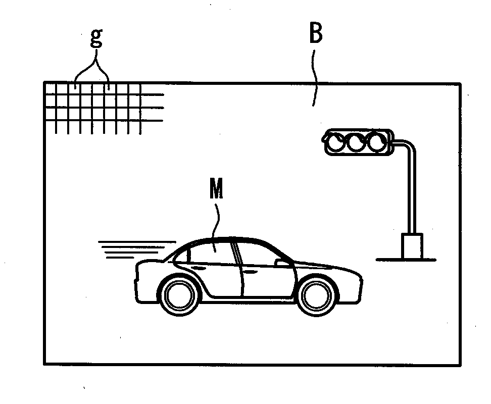
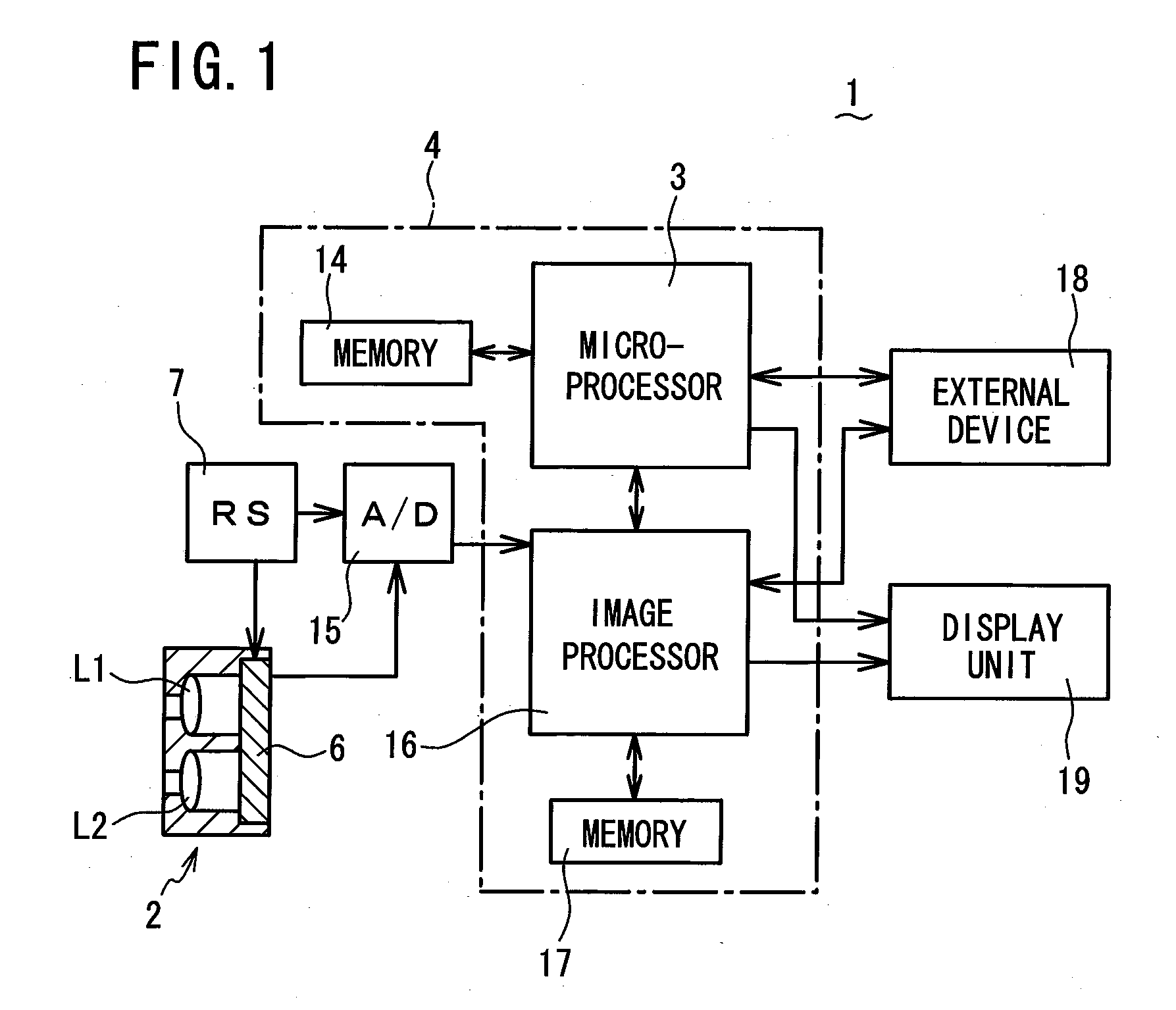
[0027]Referring to FIG. 1 to FIG. 8, a motion detection imaging device (imaging device for motion detection) 1 according to a first embodiment of the present invention will be described. As shown in FIG. 1, the motion detection imaging device 1 comprises: a compound-eye imaging device 2 for collecting light from an object so as to capture two single-eye images; and an electronic circuit 4 having a microprocessor 3 (motion detection means) as its main part. The microprocessor 3 detects movement of an object by comparing plural single-eye images.

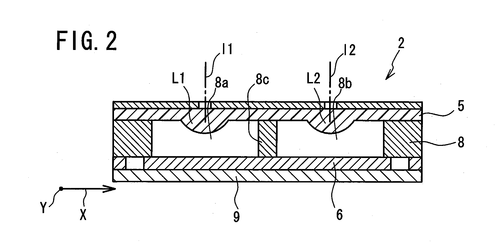
[0028]As shown in FIG. 2 and FIG. 3, the compound-eye imaging device 2 comprises: an optical lens array 5 having two optical lenses L1, L2 which have mutually parallel optical axes 11, 12, and which are arranged in the same plane and collect light from an object so as to form two single-eye images seen from different viewpoints; a solid-state imaging element 6 which captures two single-eye images A and B formed through respective optical lense...

second embodiment

[0040]Referring to FIG. 6 to FIG. 8, a motion detection imaging device 1 according to a second embodiment of the present invention will be described. The motion detection imaging device 1 of the second embodiment is similar to that of the first embodiment, except that three optical lenses L1, L2 and L3 composing the optical lens array 5 in the compound-eye imaging device 2 are arranged along the X direction as shown in FIG. 6, and that the microprocessor 3 detects acceleration of a moving objest based on three single-eye images A, B and C which are formed by the optical lenses L1, L2 and L3.

[0041]As shown in FIG. 6, the optical lenses L1, L2 and L3 in the compound-eye imaging device 2 are arranged so that the positions of single-eye images A and B formed on the solid-state imaging element 6 by the lenses L1 and L2 are displaced from each other by a predetermined distance d in the Y direction, and so that the positions of single-eye images B and C formed by the lenses L2 and L3 are s...


PUM


Abstract

A motion detection imaging device comprises: plural optical lenses for collecting light from an object so as to form plural single-eye images seen from different viewpoints; a solid-state imaging element for capturing the plural single-eye images formed through the plural optical lenses; a rolling shutter for reading out the plural single-eye images from the solid-state imaging element along a read-out direction; and a microprocessor for detecting movement of the object by comparing the plural single-eye images read out from the solid-state imaging element. The plural optical lenses are arranged so that the positions of the plural single-eye images formed on the solid-state imaging element are displaced from each other by a predetermined distance in the read-out direction, and so that the respective single-eye images formed on the solid-state imaging element partially overlap each other in the read-out direction.

Description

BACKGROUND OF THE INVENTION[0001]1. Field of the Invention[0002]The present invention relates to a motion detection imaging device, and more particularly relates to the detection of movement of a high speed moving object.[0003]2. Description of the Related Art[0004]A motion detection imaging device is known which compares plural images captured by a solid-state imaging element to detect movement of an object (refer to e.g. Japanese Laid-open Patent Publication 2002-171445). Generally a large capacity memory for storing captured images is necessary for comparing these images. However, the motion detection imaging device described in the above-cited Japanese Laid-open Patent Publication 2002-171445 can detect changes between captured images without storing these images, by exposing pixels on each pixel line at separate times and reading charges from the pixels on each pixel line at separate times.[0005]A compound-eye imaging device having a solid-state imaging element is also known (r...

Claims


Application Information

Patent Timeline
IPC IPC(8): G06K9/00H04N5/335H04N5/225H04N5/232H04N5/349H04N5/351H04N5/374
CPCG01P3/68G08G1/04G08G1/056H04N5/2251H04N5/2258H04N5/247H04N23/45H04N23/90
Inventor NAKAO, YOSHIZUMIKUGO, KOUICHITOYODA, TAKASHIMASAKI, YASUOMIYAZAKI, DAISUKE
Owner FUNAI ELECTRIC CO LTD
Why Eureka
Try Eureka