Gyro sensor

Inactive Publication Date: 2006-06-15
DENSO CORP
View PDF15 Cites 19 Cited by
  • Summary
  • Abstract
  • Description
  • Claims
  • Application Information

AI Technical Summary

Benefits of technology

[0029] The gyro sensor of the invention can generate the sensor output signal with a high degree of accuracy, because the element sensitivity of the sensing element and eventually the sensitivity of the sense signal (the second voltage signal) can be kept unchanged by controlling the ampli

Problems solved by technology

This lowers the accuracy of angular velocity detection.
Furthermore, such a system has another problem in that, if the power supply voltage VCC deviates from its rated value, although there occurs no change in the sensor output signal VYAW, there

Method used


Image

  • Gyro sensor
  • Gyro sensor
  • Gyro sensor

Examples


first embodiment

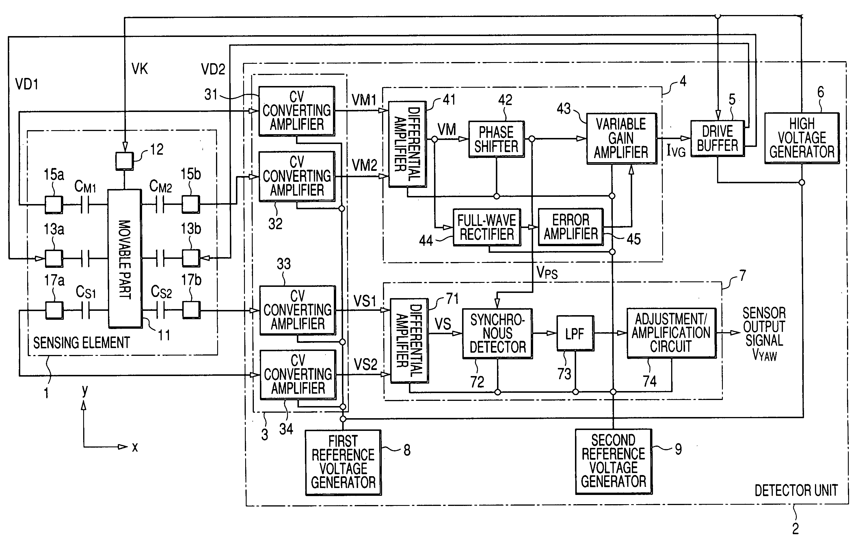
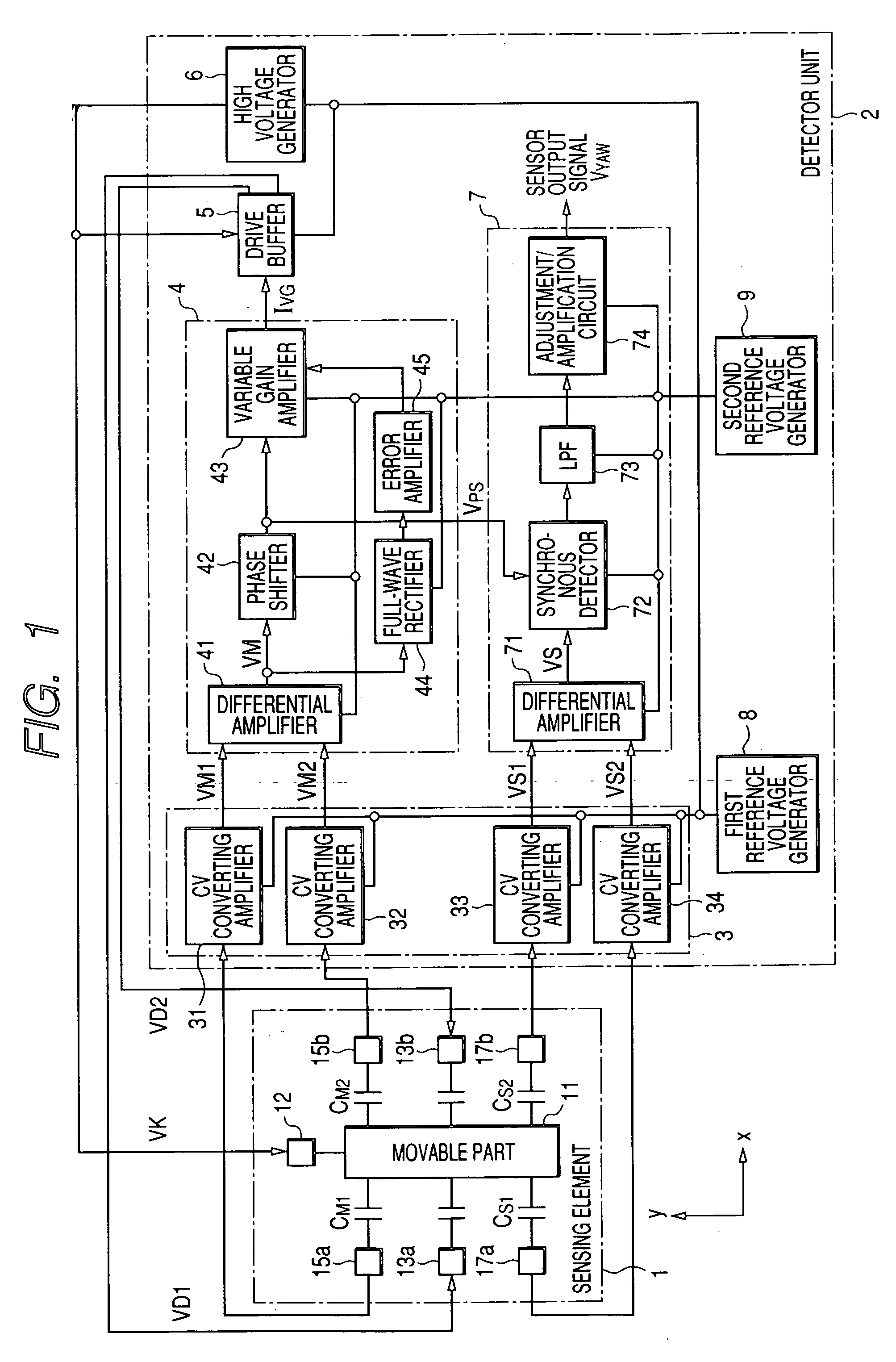
[0054]FIG. 1 is a block diagram showing a configuration of an electrostatically-driven / capacitance-detection type gyro sensor according to a first embodiment of the invention.

[0055] This gyro sensor includes a sensing element 1 having a movable part 11 which is movable on a 2-dimensional plane, and a detector unit 2 driving the sensing element 1 and detecting the angular velocity of a rotative motion imparted to the sensing element 1.

[0056] The movable part 11 is supported on a substrate mode of a single-crystal silicon material or the like by rectangular beams extending from the four corners of the substrate so as to be movable on the surface of the substrate (referred to as “motion plane” hereinafter).

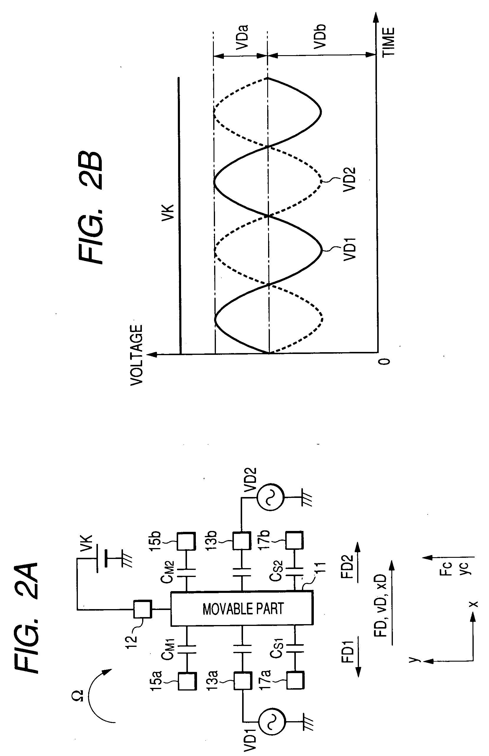
[0057] The movable part 11 is provided with a movable electrode 12 which is applied with a bias voltage VK. In close vicinity of the movable part 11, there are disposed a pair of drive electrodes 13a, 13b generating electrostatic forces with the movable part 11 in the direction al...

second embodiment

[0138] Next, a gyro sensor according to a second embodiment of the invention is explained.

[0139] Since the second embodiment is different from the first embodiment only in a part of the structure of the drive signal controller, the following explanation focuses on this different part. As shown in FIG. 8, the drive signal controller 4a of the gyro sensor of the second embodiment is configured such that the full-wave rectifier 44 rectifies the shift signal Vps(t) outputted from the phase shifter 42 instead of the composite monitor signal VM(t) outputted from the differential amplifier 41.

[0140] When there is temperature change, not only the amplitude xDa of the displacement xD(t) of the movable part 11 but also its angular frequency ωd varies depending on the Young's modulus of the base material of the sensing element 1. In this case, since the amplitude vDa of the displacing velocity vD(t) cannot be unchanged even if the amplitude xDa of the displacement xD(t) is kept unchanged as ...

third embodiment

[0147] Next, a gyro sensor according to a third embodiment of the invention is explained.

[0148] The following explanation focuses on the difference in structure between the first embodiment and the third embodiment. As shown in FIG. 10A, in the third embodiment, the drive signal controller 4b is provided with a waveform shaper 46 shaping the shift signal VPS(t) outputted from the phase shifter 42 to have a rectangular waveforms instead of the variable gain amplifier 43, the full-wave rectifier 44 and the error amplifier 45, and also the sensor output signal generator 7b is provided with a differential amplifier 71b and a synchronous detector circuit 72b instead of the differential amplifier 71 and the synchronous detector circuit 72. The output of the waveform shaper 46 is supplied to the drive buffer 5b and synchronous detector circuit 72b.

[0149] The drive buffer 5b generates two complementary signals as the drive signals VD1 (t), VD2 (t), each of which exhibits a high voltage le...


PUM


Abstract

The electrostatically-driven/capacitance-detection type gyro sensor has a sensing element including a movable part, the sensitivity of the sensing element and accordingly the sensitivity of a sensor output signal thereof being kept unchanged by controlling the amplitude of displacement or displacing velocity of the movable part and by using a reference voltage independent of variation of a power supply voltage, even there occurs a change in the vibrating state of the movable part due to temperature change or secular variation.

Description

CROSS-REFERENCE TO RELATED APPLICATION [0001] This application is related to Japanese Patent Application No. 2004-358973 filed on Dec. 10, 2004, the contents of which are hereby incorporated by reference. BACKGROUND OF THE INVENTION [0002] 1. Field of the Invention [0003] The present invention relates to a electrostatically-driven / capacitance-detection type gyro sensor [0004] 2. Description of Related Art [0005] As one type of the gyro sensor used for sensing angular velocity, there is known a electrostatically-driven / capacitance-detection type gyro sensor. As shown in FIG. 17, the gyro sensor of this type is constituted by a sensing element 101 including a movable part displaceable in a certain plane (referred to as “motion plane” hereinafter), and a detector unit 102 driving the movable part for detecting the angular velocity of rotative motion imparted to the sensing element around an axis orthogonal to the motion plane (refer to Published Japanese Translation No. 2001-515201 of ...

Claims


Application Information

Patent Timeline
IPC IPC(8): G01P15/125G01C19/56G01C19/5726
CPCG01C19/56
Inventor ITO, HAJIME
Owner DENSO CORP
Why Eureka
Try Eureka