Piezoelectric Actuator And Drive Device

Active Publication Date: 2013-03-21
MURATA MFG CO LTD
View PDF4 Cites 19 Cited by
  • Summary
  • Abstract
  • Description
  • Claims
  • Application Information

AI Technical Summary

Benefits of technology

[0025]In the first piezoelectric actuator according to the present invention, the first conductive layer made of a metal or an alloy different in color from the second electrode is formed on the first electrode. This allows the orientation of the first electrode and the second electrode to be easily identified.
[0026]In the second piezoelectric actuator according to the present invention, the first conductive layer is formed on a part of the first electrode and is made of a metal or an alloy different in color from the first electrode. Thus, since the first conductive layer serves as a mark for identification of orientation, the orientation of the first electrode and the second electrode can be easily ide

Problems solved by technology

However, the silver chloride layer has a low conductivity.
Therefore, for example, when electrical characteristics of the piezoelectric actuator are to be measured by connecting terminals of a measuring device to both the electrodes of the piezoelectric actuator, if the corresponding terminal of the measuring device is brought into contact with the silver chloride layer, the electrical characteristics of the pie

Method used


Image

  • Piezoelectric Actuator And Drive Device
  • Piezoelectric Actuator And Drive Device
  • Piezoelectric Actuator And Drive Device

Examples


Example

First Embodiment

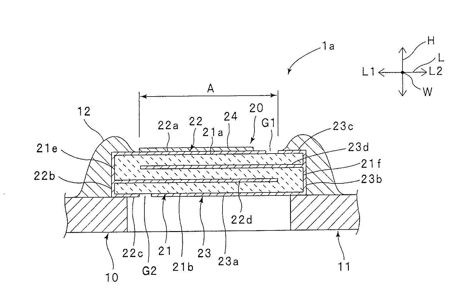
[0038]FIG. 1 is a schematic cross-sectional view of a drive device according to a first embodiment. FIG. 2 is a schematic plan view of a piezoelectric actuator according to the first embodiment. For convenience of description, a conductive layer is indicated by hatching in FIG. 2.

[0039]The drive device 1a illustrated in FIG. 1 is designed to drive a magnetic head of a hard disk drive. The drive device 1a includes a fixed member 10 and a driven member 11 having the magnetic head. The fixed member 10 and the driven member 11 are connected to each other by a piezoelectric actuator 20. Therefore, when the piezoelectric actuator 20 is driven, the driven member 11 is displaced with respect to the fixed member 10. This drives the magnetic head attached to the driven member 11.

[0040]The fixed member 10 and the driven member 11 are not particularly limited. The fixed member 10 and the driven member 11 each may be formed, for example, by an insulating substrate that has a circ...

Example

Second Embodiment

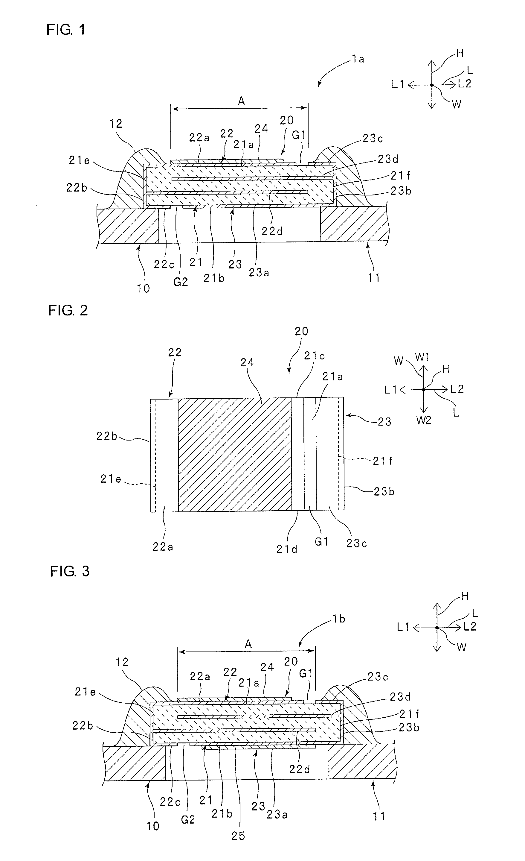
[0074]FIG. 3 is a schematic cross-sectional view of a drive device according to a second embodiment.

[0075]In the first embodiment described above, the conductive layer 24 is formed on the first electrode 22, whereas no conductive layer is formed on the second electrode 23. However, the present invention is not limited to this configuration.

[0076]For example, as illustrated in FIG. 3, in addition to the conductive layer 24 on the first electrode 22, a conductive layer 25 of metal or alloy may be formed on the second electrode 23. In this case, it is preferable that the conductive layer 25 be different in at least one of color and shape from the conductive layer 24. This makes it easier to identify the orientation of the piezoelectric actuator 20.

[0077]Like the conductive layer 24, the conductive layer 25 is made of a metal or an alloy having a high conductivity. Therefore, even with the conductive layer 25, it is possible to suppress a decrease in accuracy of measure...

Example

Third Embodiment

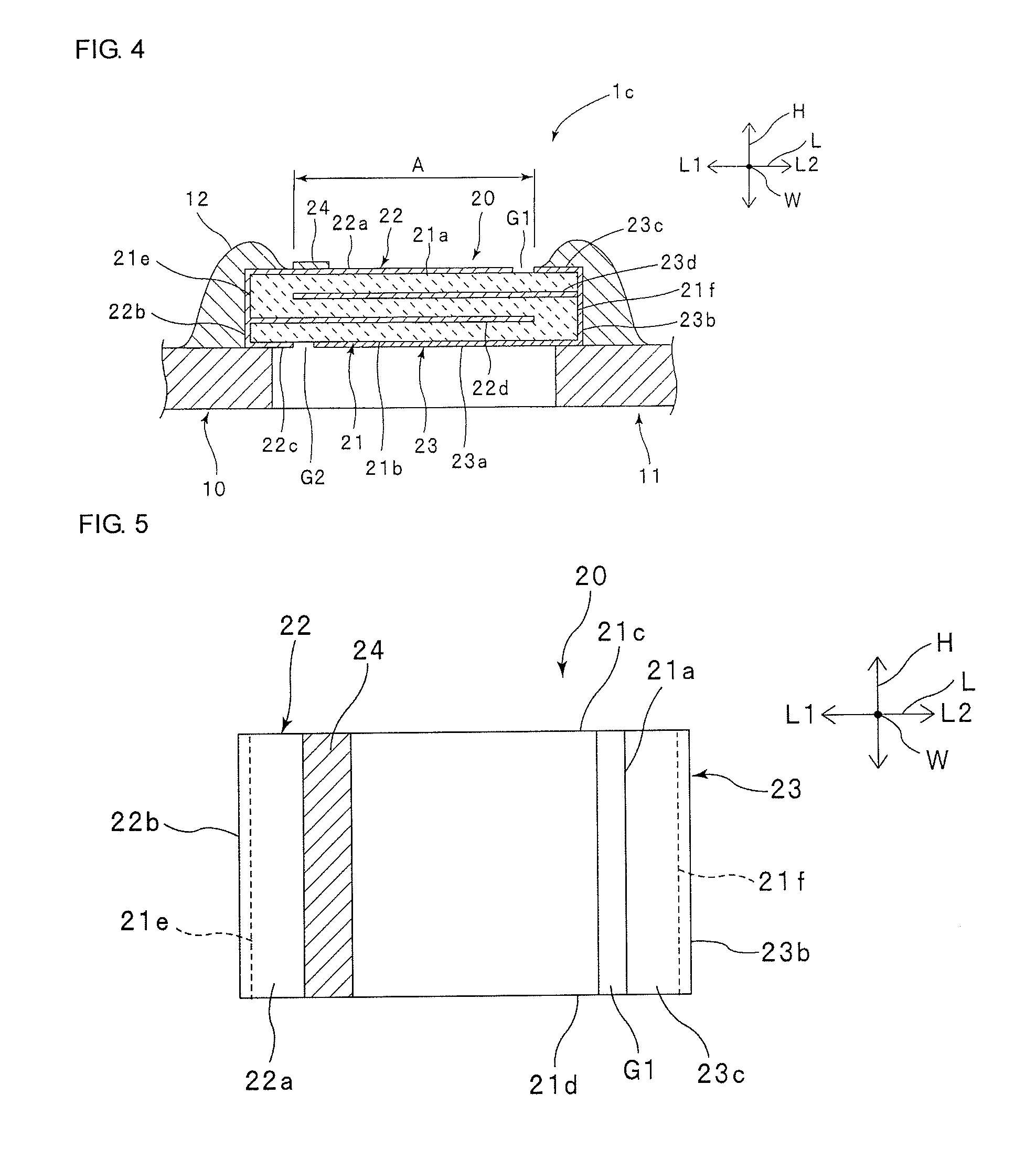
[0085]FIG. 4 is a schematic cross-sectional view of a drive device according to a third embodiment. FIG. 5 is a schematic plan view of a piezoelectric actuator according to the third embodiment. For convenience of description, a conductive layer is indicated by hatching in FIG. 5.

[0086]In the first embodiment described above, the conductive layer 24 is formed to cover substantially the entire portion of the first electrode 22 located within the excitation part A. However, the present invention is not limited to this configuration. For example, as illustrated in FIG. 4 and FIG. 5, the conductive layer 24 may be formed linearly in the width direction W. Even with this configuration, it is possible, as in the first embodiment, to effectively suppress spreading of the solder 12 to the excitation part A.

[0087](First to Third Modifications)

[0088]FIG. 6 is a schematic plan view of a piezoelectric actuator according to a first modification, and illustrates a formation patter...


PUM


Abstract

A piezoelectric actuator that includes a piezoelectric substrate, first and second electrodes, and a conductive layer. The first and second electrodes are configured to apply a voltage to the piezoelectric substrate. The conductive layer is formed on the first electrode. The conductive layer is made of a metal or an alloy different in color from the second electrode.

Description

CROSS REFERENCE TO RELATED APPLICATIONS[0001]The present application is a continuation of International application No. PCT / JP2011 / 060427, filed Apr. 28, 2011, which claims priority to Japanese Patent Application No. 2010-113319, filed May 17, 2010, the entire contents of each of which are incorporated herein by reference.FIELD OF THE INVENTION[0002]The present invention relates to a piezoelectric actuator used, for example, for driving a magnetic head of a hard disk drive, and also relates to a drive device including the piezoelectric actuator.BACKGROUND OF THE INVENTION[0003]Conventionally, piezoelectric actuators have been widely used, for example, for driving a magnetic head of a hard disk drive.[0004]A piezoelectric actuator includes a piezoelectric substrate polarized in a predetermined direction. Therefore, when mounted on a device, the piezoelectric actuator needs to be oriented in accordance with the direction of polarization. This means that the orientation of the piezoele...

Claims


Application Information

Patent Timeline
IPC IPC(8): H01L41/047
CPCG11B5/4813G11B5/482H01L41/0986H01L41/047H01L41/0472G11B5/4873G11B5/483G11B5/5552H10N30/87H10N30/872H10N30/877H10N30/206
Inventor NAKAMURA, KIMITOSHINAKATANI, HIROSHINISHIKAWA, MASANAGAKITAGAWA, SACHIO
Owner MURATA MFG CO LTD
Why Eureka
Try Eureka