

Multi-functional polarity-correcting plugging-coupling switching device
- Summary
- Abstract
- Description
- Claims
- Application Information
AI Technical Summary
Benefits of technology
Problems solved by technology
Method used
Image

Examples
Embodiment Construction
[0037]The following descriptions are exemplary embodiments only, and are not intended to limit the scope, applicability or configuration of the invention in any way. Rather, the following description provides a convenient illustration for implementing exemplary embodiments of the invention. Various changes to the described embodiments may be made in the function and arrangement of the elements described without departing from the scope of the invention as set forth in the appended claims.
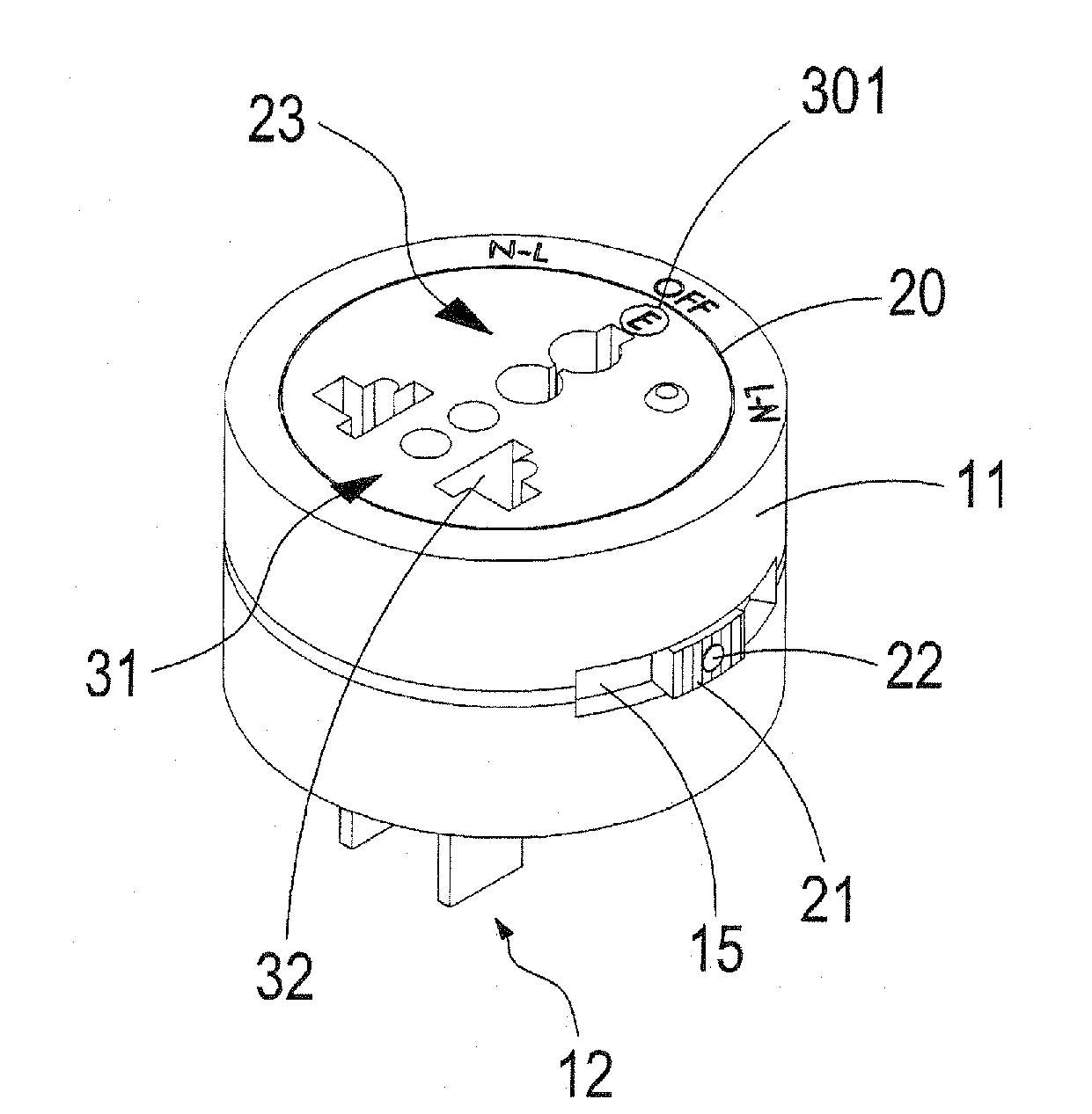
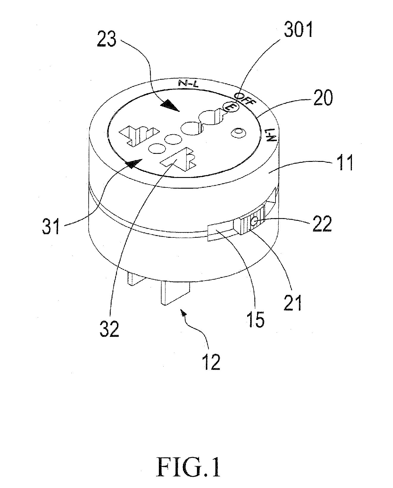
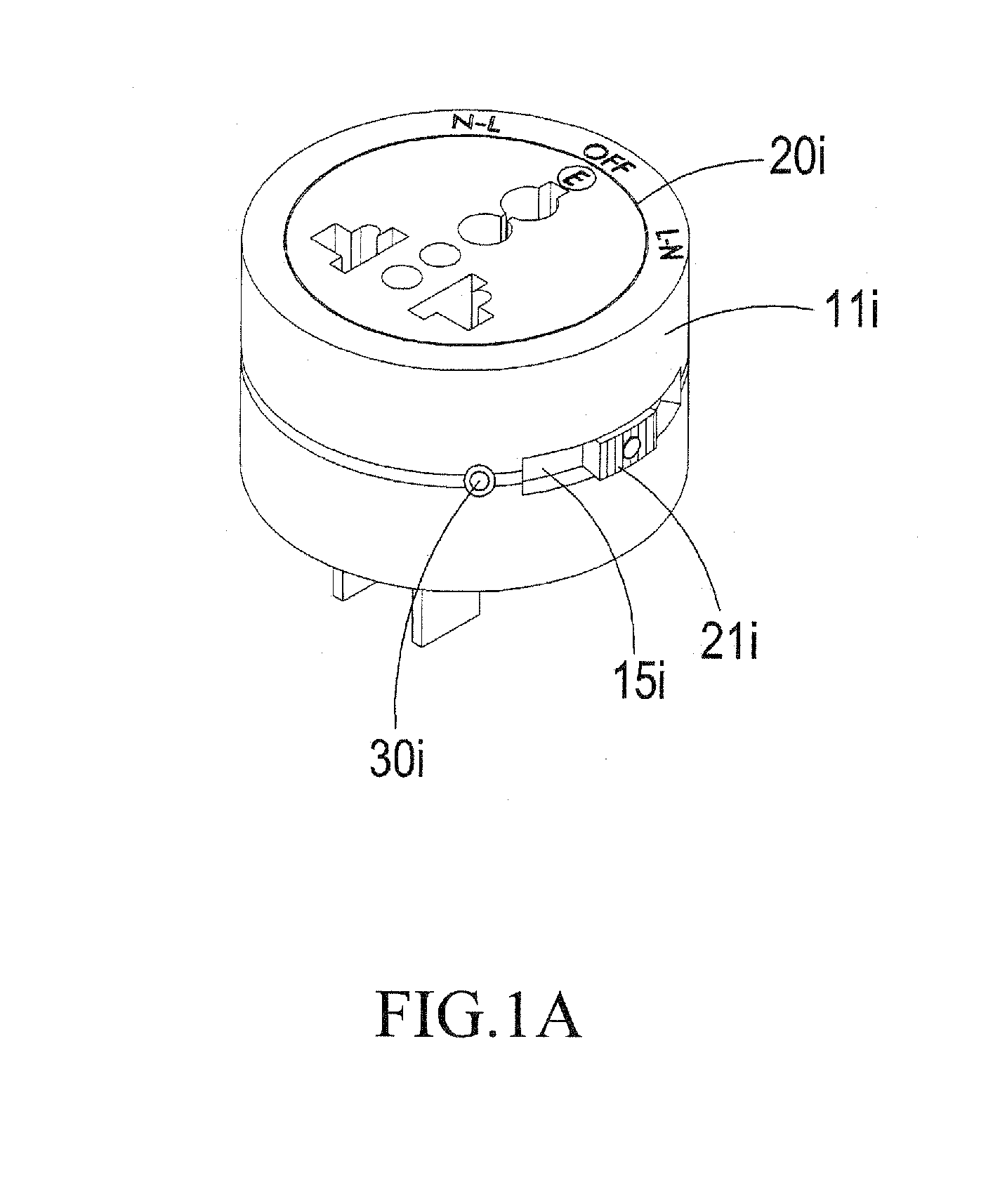
[0038]Referring to FIGS. 1, 2, 3, 3A, 3B, 4, 4A, 5, and 5A, which are respectively a perspective view and a cross-sectional view of a multi-functional polarity-correcting plugging-coupling switching device according to a preferred embodiment of the present invention, a top plan view of an insulation enclosure of the switching device, and first to sixth illustrations of polarization setting of the switching device, the switching device of the present invention comprises an insulation enclosure 11, a ...
PUM
 Abstract
Description
Claims
Application Information