
Omni-directional Lens in Sundials and Solar Compasses

Inactive Publication Date: 2009-02-19
THE TRUSTEES OF COLUMBIA UNIV IN THE CITY OF NEW YORK
View PDF15 Cites 10 Cited by
  • Summary
  • Abstract
  • Description
  • Claims
  • Application Information

AI Technical Summary

Benefits of technology

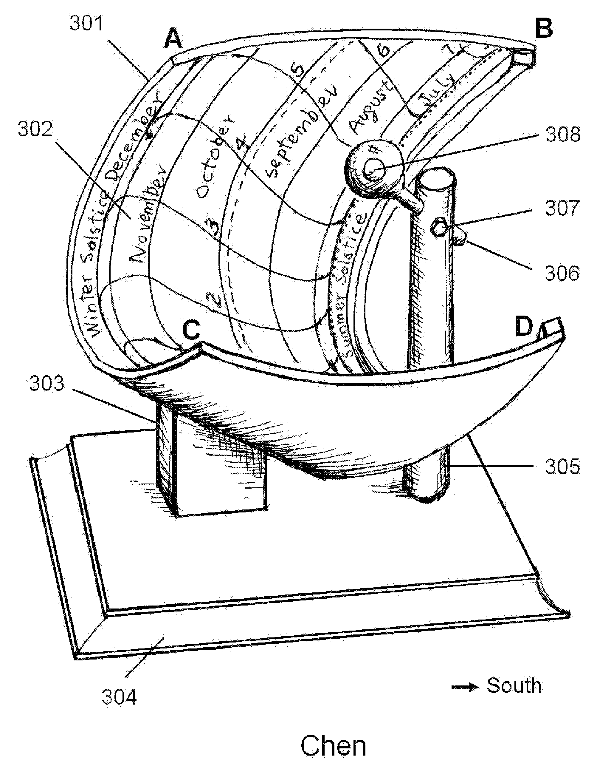
[0009]The center of the light spot has a much higher intensity than the direct sunlight. It makes the center spot very easy to be identified. To avoid burning the panel, at least one of the spheres is made of a heat absorbing material, for example, doped with copper sulfate. With copper sulfate, only the blue light can go through the lens. Furthermore, by using a panel with dark blue background, the brightness of the area exposed to direct sunlight is substantially reduced, and the bright blue spot projected through the omni-directional lens becomes even more eye-catching.
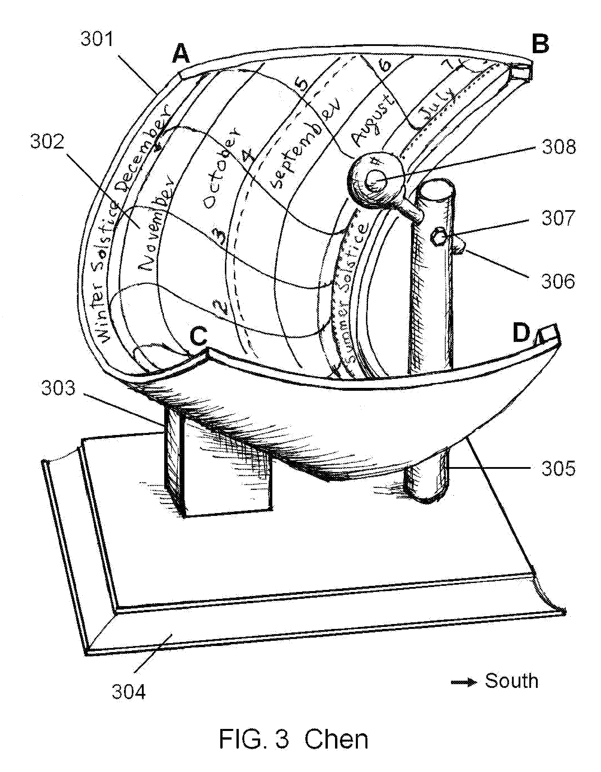
[0010]Because of the large depth of field, the center of the sun can be projected on a cylindrical panel without loosing its sharpness over the entire area. A precise printout of the path of the sun can be easily made, which can provide a highly accurate reading. Because both the day of the year and the time of the day can be identified, the correction due to the equation of time is done automatically and accurately. By using two panels per year (from one solstice to another solstice), the daylight saving time can be marked directly.
[0011]If the time and the date are known, the instrument can be configured as a compass. The principle of the solar compass is not new. However, to use existing solar compasses, the instantaneous position of the sun must be calculated from astronomical data one by one, and the operator must wait the predetermined time to come. This consumes a lot of time and requires a profound knowledge on astronomy. For the solar compass based on the omni-directional lens, the astronomical information is explicitly marked on the panel. Therefore, it operation is independent of time, very intuitive, and easy to use.

Problems solved by technology

This consumes a lot of time and requires a profound knowledge on astronomy.

Method used


Image

  • Omni-directional Lens in Sundials and Solar Compasses
  • Omni-directional Lens in Sundials and Solar Compasses
  • Omni-directional Lens in Sundials and Solar Compasses

Examples


Embodiment Construction

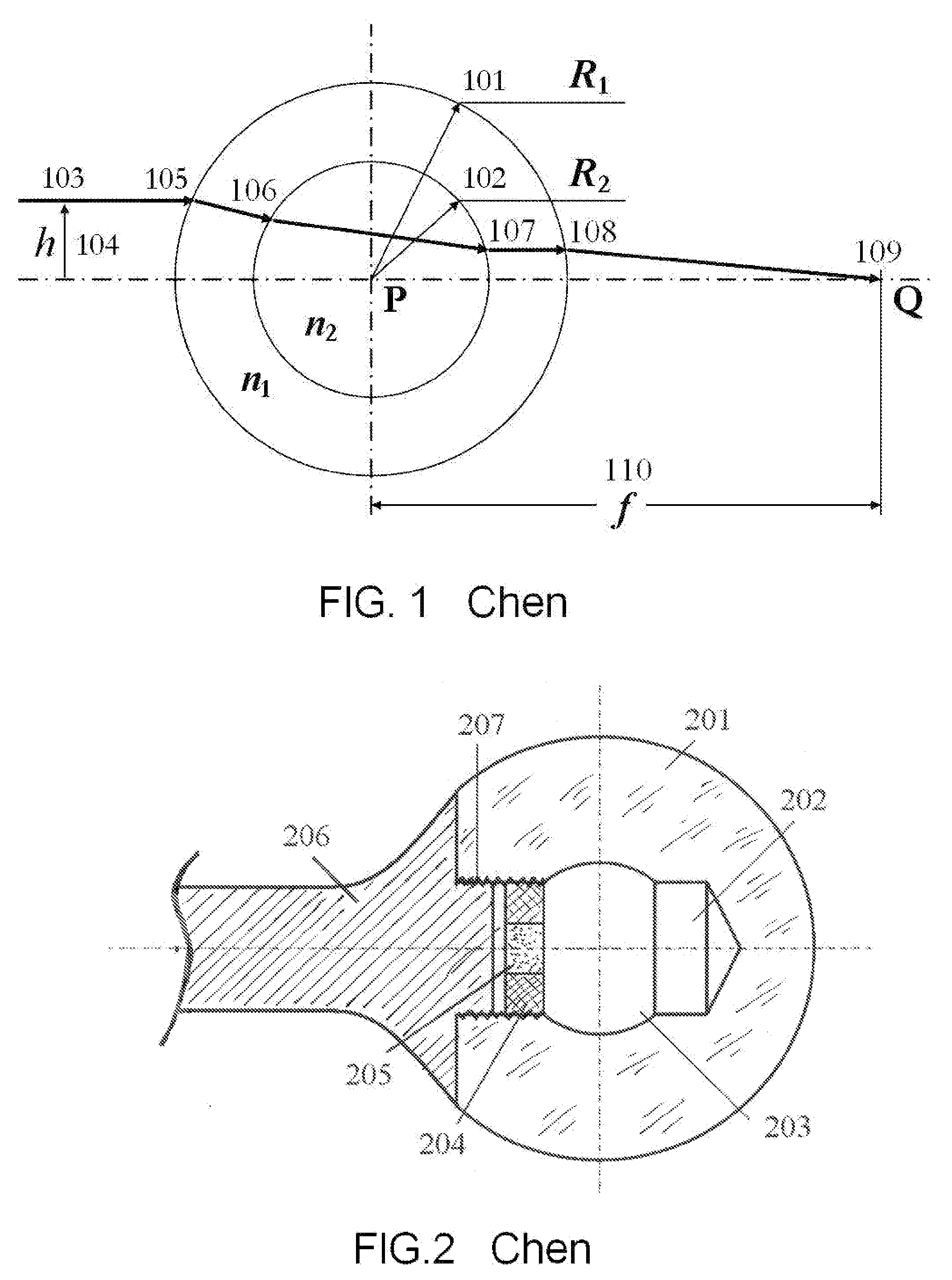
[0019]The principle of the omni-directional lens is shown in FIG.1. It is a sphere comprises two concentric components. The outer sphere 101 with radius R1 is made of a transparent material with index of refraction n1. The inner sphere 102 with radius R2 is made of another transparent material of index of refraction n2. When a light beam 103 impinges on the lens with an offset h from the axis, owing to the difference in the index of refraction, the beam is refracted four times on the four surfaces, 105, 106, 107, and 108. Detailed mathematical analysis shows that under the conditions n1>n2 and

R2R1>n1-n2(n1-1)n2,

all rays with the same h will converge at a point Q (109) on the axis with a finite distance f (110) from the center of the sphere P. In general, for rays with different h, the focal length f is different. Since the rays with the same offset h converge at the same spot at the axis, it creates a light spot with very high intensity. However, all the rays with different h will b...


PUM


Abstract

To date, the existing sundials and solar compasses use a gnomon, such as a stylet, to project a shadow under the sun on a marked surface to find the time or the true north. Because of the fussiness of the shadow and the dependence of the position of the sun with the day of the year (equation of time), the accuracy is low. The present invention discloses an omni-directional lens, which can focus the sun beam into a sharp spot with a long depth of field. By projecting the spot on a cylindrical panel, both the day of the year and the time of the day can be read off simultaneously with very high accuracy. Because of the simultaneous displaying of time and date, no equation-of-time correction is required. If the time is known, the true north can be determined with high accuracy, and the device becomes a reliable and easy-to-use solar compass.4,384,408Bohlayer19834,520,572Spilhaus19854,835,875Fuller19894,945,644Fuller19905,197,199Shrader19935,425,178Steele19956,301,793Gottesman20016,604,290Gottesman20037,114,262Andrewes20069,428Burt18364,899.451Dandurand19905,425,178Steele19955,459,931Waltho1995

Description

BACKGROUND OF THE INVENTION[0001]1. Field of the Invention[0002]The present invention discloses to a new type of optical device, the omni-directional lens, which can focus the sun beam from all directions onto a sharp spot with a long depth of field, which then applied to sundials and solar compasses. The sundials and solar compasses made with the omni-directional lens are easy to use and accurate.[0003]2. Description of the Prior Art[0004]Sundial is one of the earliest scientific instruments created by the mankind. Thousands of years ago, almost every culture of the world independently discovered the principle of determine the day in a year and the time in a day by observing the position of the sun, and invented some type of the sundial. Although the mechanical clock was invented in the 16th century, until late 19th century, the sundial was still used as a reliable time piece in Europe. Even in recent years, novel types of sundials are continuously being invented, as shown in the R...

Claims


Application Information

Patent Timeline
IPC IPC(8): G01C17/34G02B3/00
CPCG01C17/34G02B3/12G02B3/00
Inventor CHEN, CHENGJUN JULIAN
Owner THE TRUSTEES OF COLUMBIA UNIV IN THE CITY OF NEW YORK
Learn More