MEMS resonant accelerometer having improved electrical characteristics

a resonant accelerometer and micro-electromechanical technology, applied in acceleration measurement, measurement devices, instruments, etc., can solve the problem that none of the proposed sensing structures has been fully satisfactory in terms of dimensions and electrical characteristics

Active Publication Date: 2011-03-10
STMICROELECTRONICS SRL
View PDF19 Cites 27 Cited by
  • Summary
  • Abstract
  • Description
  • Claims
  • Application Information

AI Technical Summary

Benefits of technology

[0019]One embodiment is a resonant accelerometer, having improved physical and electrical characteristics. The resonant accelerometer includes a proof mass, a first anchoring region coupled to the substrate, and a first elastic element coupled to the first anchoring region and the proof mass, the first elastic element configured to allow movement along a sensing axis in response to an external acceleration. The resonant accelerometer also includes a second anchoring region coupled to the substrate, a second elastic element coupled to the second anchoring region and to the proof mass, the second elastic element configured to allow movement along the sensing axis in response to the external acceleration. A first resonating element is coupled to the proof mass via the first elastic element, the first resonating element having a resonant frequency and configured to generate a first variation of the resonant frequency in response to a first axial stress when the proof mass moves along the sensing axis. A second resonating element is coupled to the proof mass via the second elastic element, the second resonating element having the resonant frequency and configured to generate a second variation of the resonant frequency in response to a second axial stress when the proof mass moves along the sensing axis, the second axial stress being substantially opposite to the first axial stress, and the second variation being substantially opposite to the first variation.

Problems solved by technology

None of the proposed sensing structures has proven to be fully satisfactory in terms of the dimensions and electrical characteristics of the resulting accelerometer sensors.

Method used


Image

  • MEMS resonant accelerometer having improved electrical characteristics
  • MEMS resonant accelerometer having improved electrical characteristics
  • MEMS resonant accelerometer having improved electrical characteristics

Examples


Embodiment Construction

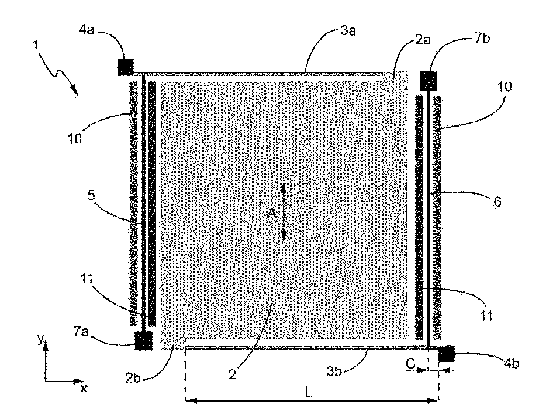
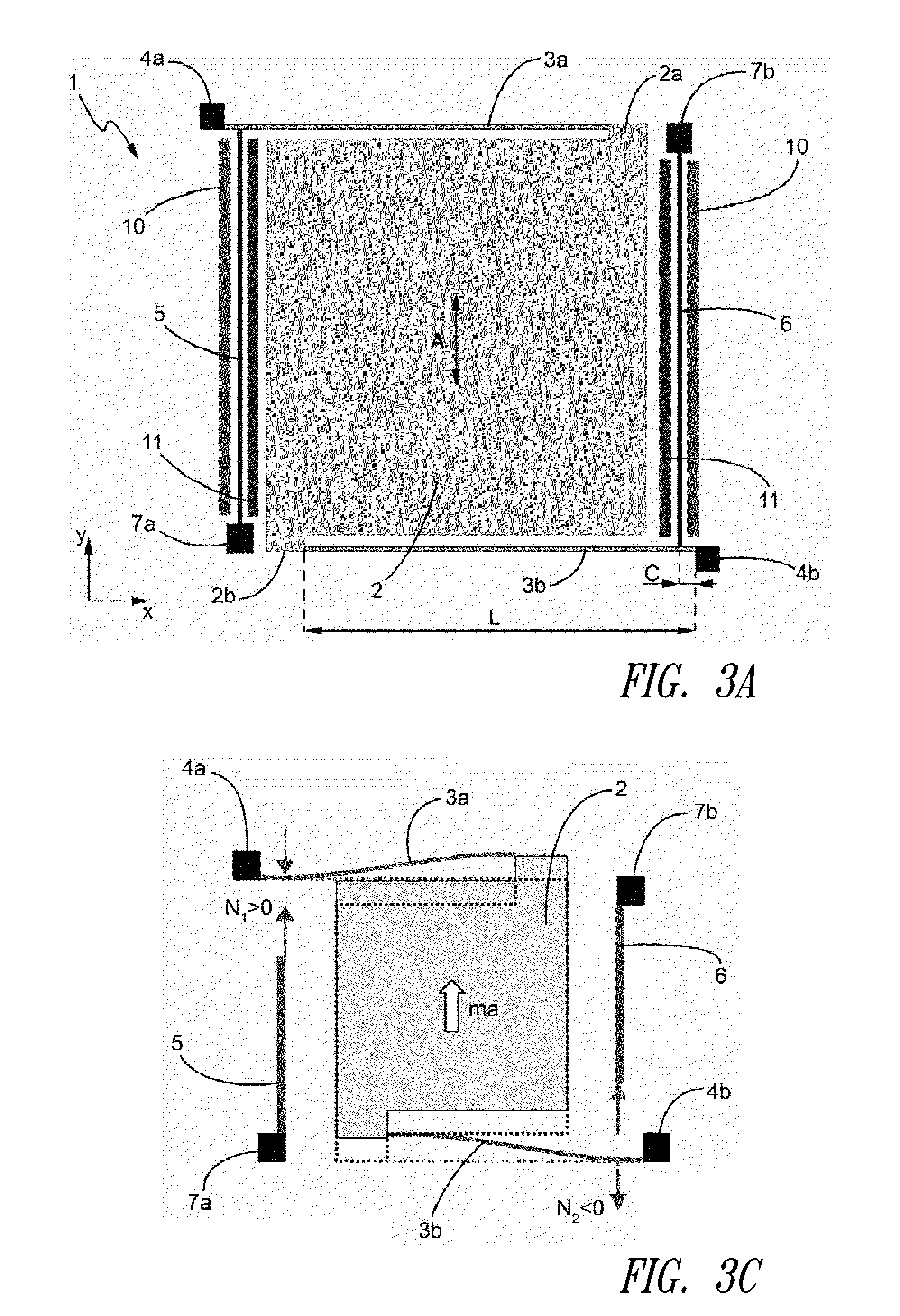
[0029]FIGS. 3a, 3b show a MEMS sensing structure of a resonant uniaxial accelerometer according to a first embodiment of the present disclosure, denoted as a whole by 1.

[0030]The sensing structure 1 includes a proof (or sensing) mass 2, having a generically square shape (in a main plane of extension xy) and two projections 2a, 2b, extending from diagonally opposite corners of the proof mass 2 (e.g., from the top right and bottom left corner in FIG. 3a).

[0031]The proof mass 2 is suspended by means of two springs 3a, 3b which are so configured to restrain its movement to a single uniaxial translation, along axis A (parallel to reference axis y); springs have an elongated structure extending in a direction transversal to the axis A (e.g., orthogonally thereto, parallel to reference axis x). In more detail, springs 3a, 3b can be of a single beam (FIG. 3a) or a folded beam type (having an “S-shape,”FIG. 3b).

[0032]Springs 3a, 3b are anchored to a substrate of the sensor (not shown) via re...


PUM


Abstract

A MEMS resonant accelerometer is disclosed, having: a proof mass coupled to a first anchoring region via a first elastic element so as to be free to move along a sensing axis in response to an external acceleration; and a first resonant element mechanically coupled to the proof mass through the first elastic element so as to be subject to a first axial stress when the proof mass moves along the sensing axis and thus to a first variation of a resonant frequency. The MEMS resonant accelerometer is further provided with a second resonant element mechanically coupled to the proof mass through a second elastic element so as to be subject to a second axial stress when the proof mass moves along the sensing axis, substantially opposite to the first axial stress, and thus to a second variation of a resonant frequency, opposite to the first variation.

Description

BACKGROUND[0001]1. Technical Field[0002]The present disclosure relates to a MEMS (Micro Electro Mechanical System) resonant accelerometer having improved electrical characteristics.[0003]2. Description of the Related Art[0004]As is known, MEMS accelerometers play an important role in the field of sensors with applications in various contexts including automotive, vibration monitoring and portable electronics. The large number of micro-accelerometers proposed in the literature and nowadays present on the market can be grouped in three classes, on the basis of the sensing principle: capacitive, resonant and piezoresistive. The more common surface micromachined accelerometers belong to the first class, but also resonant accelerometers have been produced by surface micromachining technology. In this respect, reference may be made to the following papers:[0005]M. Aikele, K. Bauer, W. Ficker, F. Neubauer, U. Prechtel, J. Schalk, H. Seidel “Resonant accelerometer with self-test”, Sensors a...

Claims


Application Information

Patent Timeline
Patent Type & Authority Applications(United States)
IPC IPC(8): G01P15/10
CPCG01P15/097G01P15/10
Inventor SIMONI, BARBARACOMI, CLAUDIACORIGLIANO, ALBERTO
Owner STMICROELECTRONICS SRL
Why Eureka
Try Eureka