Supercharge Your Innovation With Domain-Expert AI Agents!

Mask defect testing apparatus

a mask and defect technology, applied in the field of mask defect testing apparatus, can solve the problems of large loss in all manufacturing processes using the corresponding metal mask, damage to the pattern of the mask, and the test camera cannot only approach

Inactive Publication Date: 2011-03-17
SAMSUNG DISPLAY CO LTD
View PDF8 Cites 4 Cited by
  • Summary
  • Abstract
  • Description
  • Claims
  • Application Information

AI Technical Summary

Benefits of technology

[0008]Aspects of the present invention provide a mask defect testing apparatus that is capable of precisely and stably testing for presence of a defect of a metal mask.
[0019]According to aspects of the present invention, the mask defect test apparatus can precisely and stably test for the presence of a defect of the metal mask.

Problems solved by technology

However, in some cases defects can occur, such as where fine foreign materials are attached to the metal mask, resulting in damage to the patterns in the mask.
These defects can cause a large loss in all the manufacturing processes using the corresponding metal mask.
However, since a clamp of a jig fixing an edge of the metal mask generally has a structure that protrudes upward, the test camera can only approach the metal mask fixed to the jig within a range that does not collide with the jig.
In other words, due to the structure of the jig fixing the metal mask, the camera is limited in approaching the metal mask to be tested or testing an edge portion of the metal mask.
Therefore, the presence of a defect of the metal mask is not precisely and stably tested.

Method used


Image

  • Mask defect testing apparatus
  • Mask defect testing apparatus
  • Mask defect testing apparatus

Examples


Embodiment Construction

[0026]Reference will now be made in detail to the present embodiments of the present invention, examples of which are illustrated in the accompanying drawings, wherein like reference numerals refer to the like elements throughout. The embodiments are described below in order to explain the present invention by referring to the figures.

[0027]Further, since sizes and thicknesses of constituent members shown in the accompanying drawings are arbitrarily given for better understanding and ease of description, aspects of the present invention are not limited to the illustrated sizes and thicknesses. In the drawings, the thickness of layers, regions, etc., are exaggerated for clarity and ease of understanding. It will be understood that when an element such as a layer, film, region, or substrate is referred to as being “on” another element, it can be directly on the other element or separated by intervening elements.

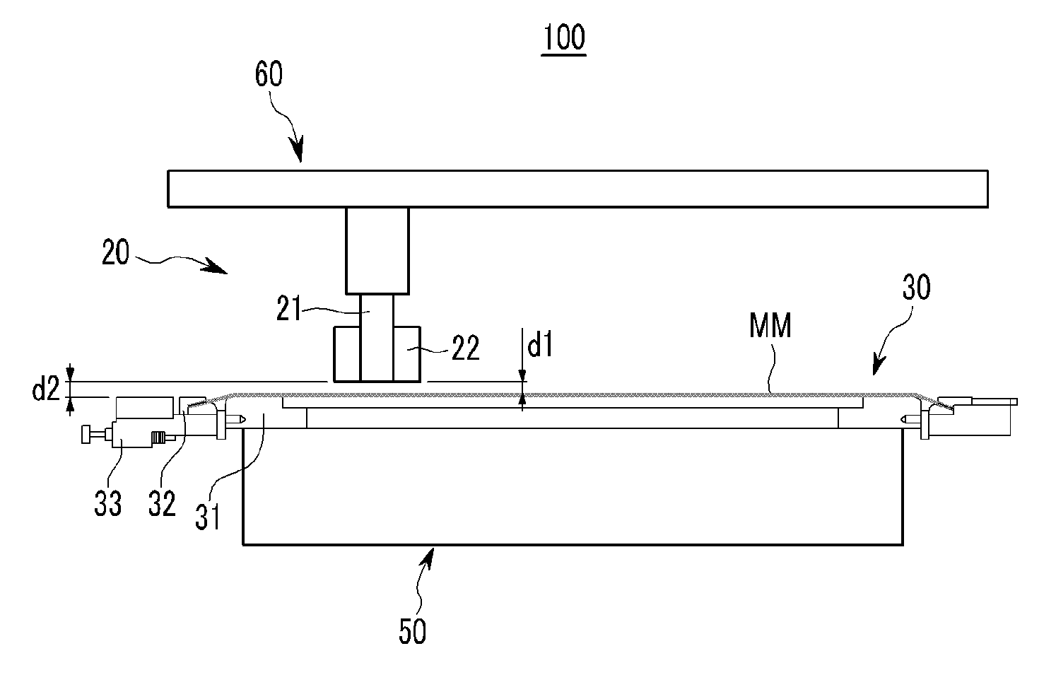
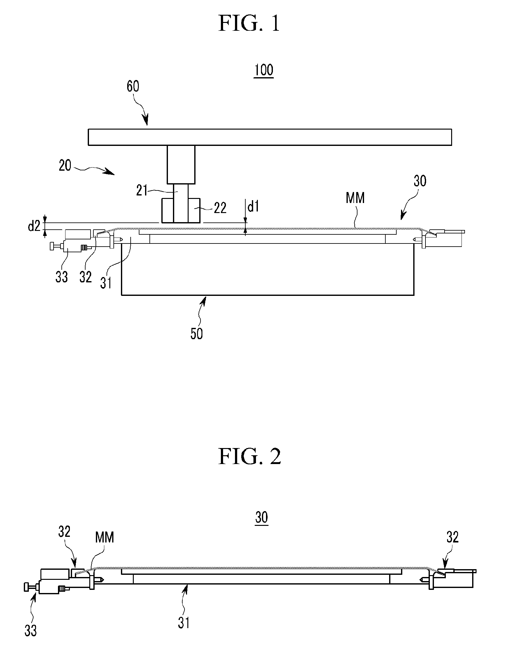
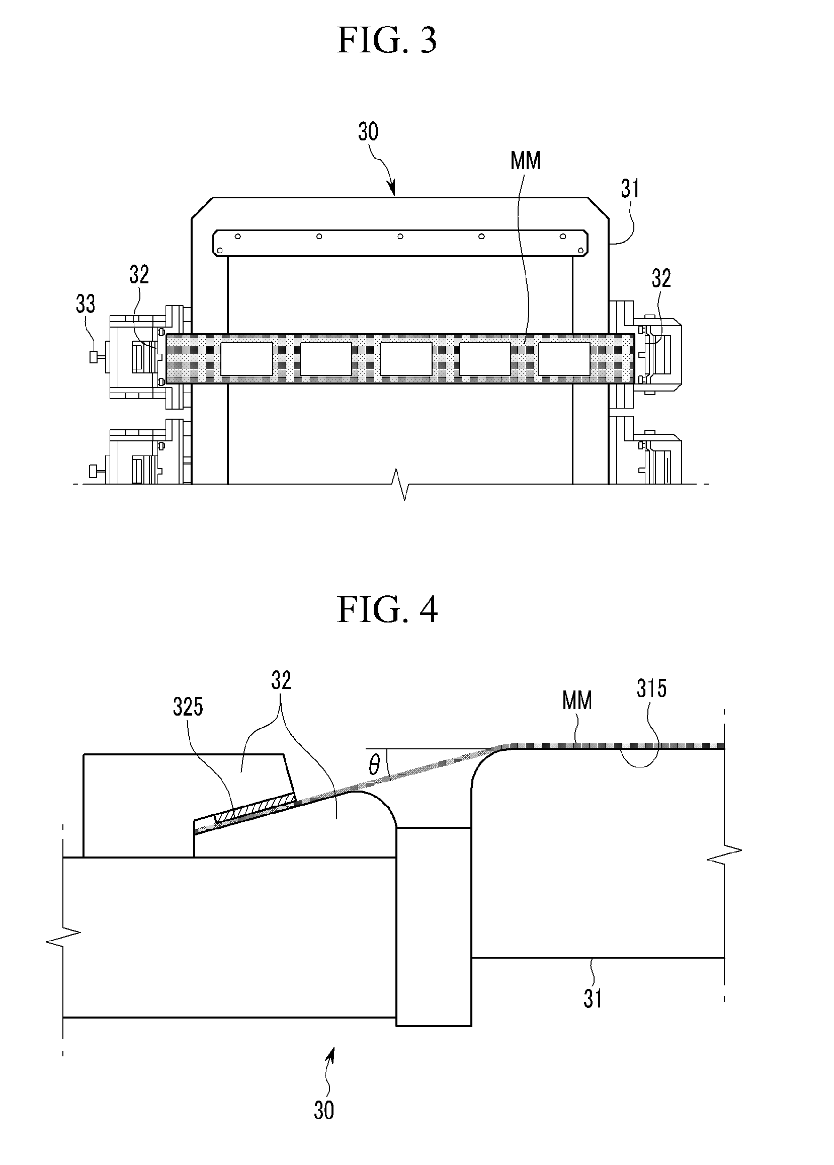
[0028]Hereinafter, a mask defect test apparatus 100 according to an embodi...


PUM

PropertyMeasurementUnit
angleaaaaaaaaaa
inclined angleaaaaaaaaaa
angleaaaaaaaaaa

Abstract

A mask defect test apparatus, including a tension jig unit having a supporter on which a metal mask to be tested is located, a clamp part disposed at both sides of the supporter to fix opposite edges of the metal mask, and a tension part to apply a tension force to the metal mask fixed by the clamp part; and a test unit to test the metal mask fixed by the tension jig unit. A vertical distance between the metal mask located on the supporter and the test unit is less than or equal to a vertical distance between the tension jig unit and the test unit.

Description

CROSS-REFERENCE TO RELATED APPLICATIONS[0001]This application claims the benefit of Korean Application No. 10-2009-0085852, filed in the Korean Intellectual Property Office on Sep. 11, 2009, the disclosure of which is incorporated herein by reference.BACKGROUND OF THE INVENTION[0002]1. Field of the Invention[0003]Aspects of the present invention relate generally to a mask defect testing apparatus, and more specifically, to a mask defect testing apparatus that tests whether a mask used for a display panel manufacturing process is defective or not.[0004]2. Description of the Related Art[0005]Display panel manufacturing processes generally employ various kinds of masks. For example, a metal mask is used for precise processes. However, in some cases defects can occur, such as where fine foreign materials are attached to the metal mask, resulting in damage to the patterns in the mask. These defects can cause a large loss in all the manufacturing processes using the corresponding metal ma...

Claims


Application Information

Patent Timeline
Patent Type & Authority Applications(United States)
IPC IPC(8): G01N3/08G01N21/956
CPCG03F1/84G03F1/20H01L22/00
Inventor PARK, SI-YOUNG
Owner SAMSUNG DISPLAY CO LTD
Features
  • R&D
  • Intellectual Property
  • Life Sciences
  • Materials
  • Tech Scout
  • Unparalleled Data Quality
  • Higher Quality Content
  • 60% Fewer Hallucinations
Learn More