Imaging module with fixed-focus lens

a technology of imaging module and fixed focus, which is applied in the field of imaging modules, can solve the problems of increasing the cost of imaging modules, the difficulty of making screw threads on imaging modules, and the limited design options of these components

Inactive Publication Date: 2011-03-31
HON HAI PRECISION IND CO LTD
View PDF11 Cites 15 Cited by
  • Summary
  • Abstract
  • Description
  • Claims
  • Application Information

AI Technical Summary

Benefits of technology

[0004]With the ongoing progress of imaging technology, imaging modules are becoming more and more compact. An imaging module often employs a fixed-focus lens. In assembly of the imaging module, the fixed-focus lens is positioned such that the focus of the fixed-focus lens is on an imaging surface of an image sensor of the imaging module. Then the fixed-focus lens is fixed in position relative to the image sensor. Currently, the position of the fixed-focus lens is adjusted by screwing. However, it is difficult to make a screw thread on the imaging module, and the need for a screw thread increases the cost of the imaging module. In addition, the shape of the fixed-focus lens, and associated optical components such as a lens barrel, must be circular. Therefore, design options for these components are limited.

Problems solved by technology

However, it is difficult to make a screw thread on the imaging module, and the need for a screw thread increases the cost of the imaging module.
Therefore, design options for these components are limited.

Method used


Image

  • Imaging module with fixed-focus lens
  • Imaging module with fixed-focus lens
  • Imaging module with fixed-focus lens

Examples


Embodiment Construction

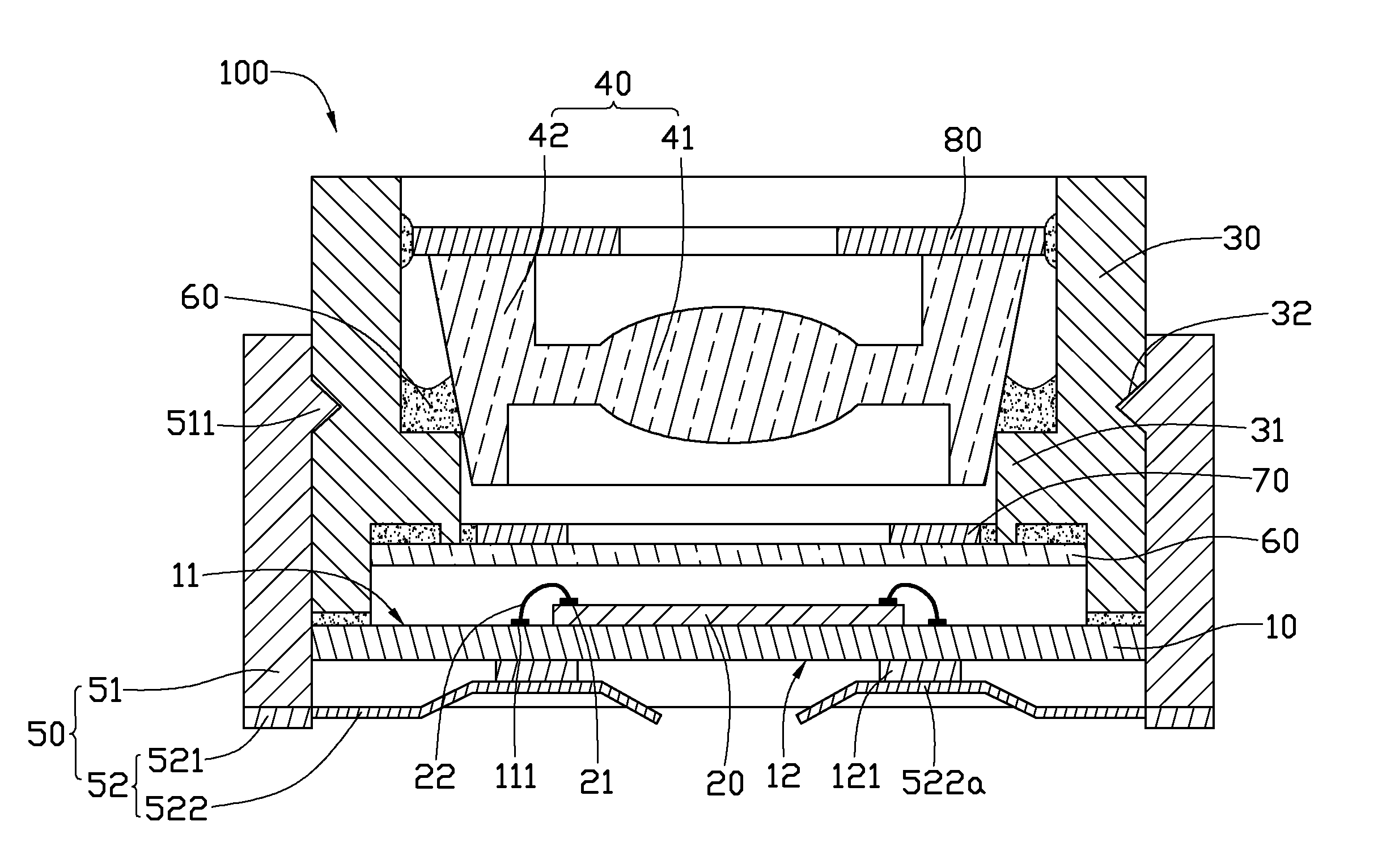
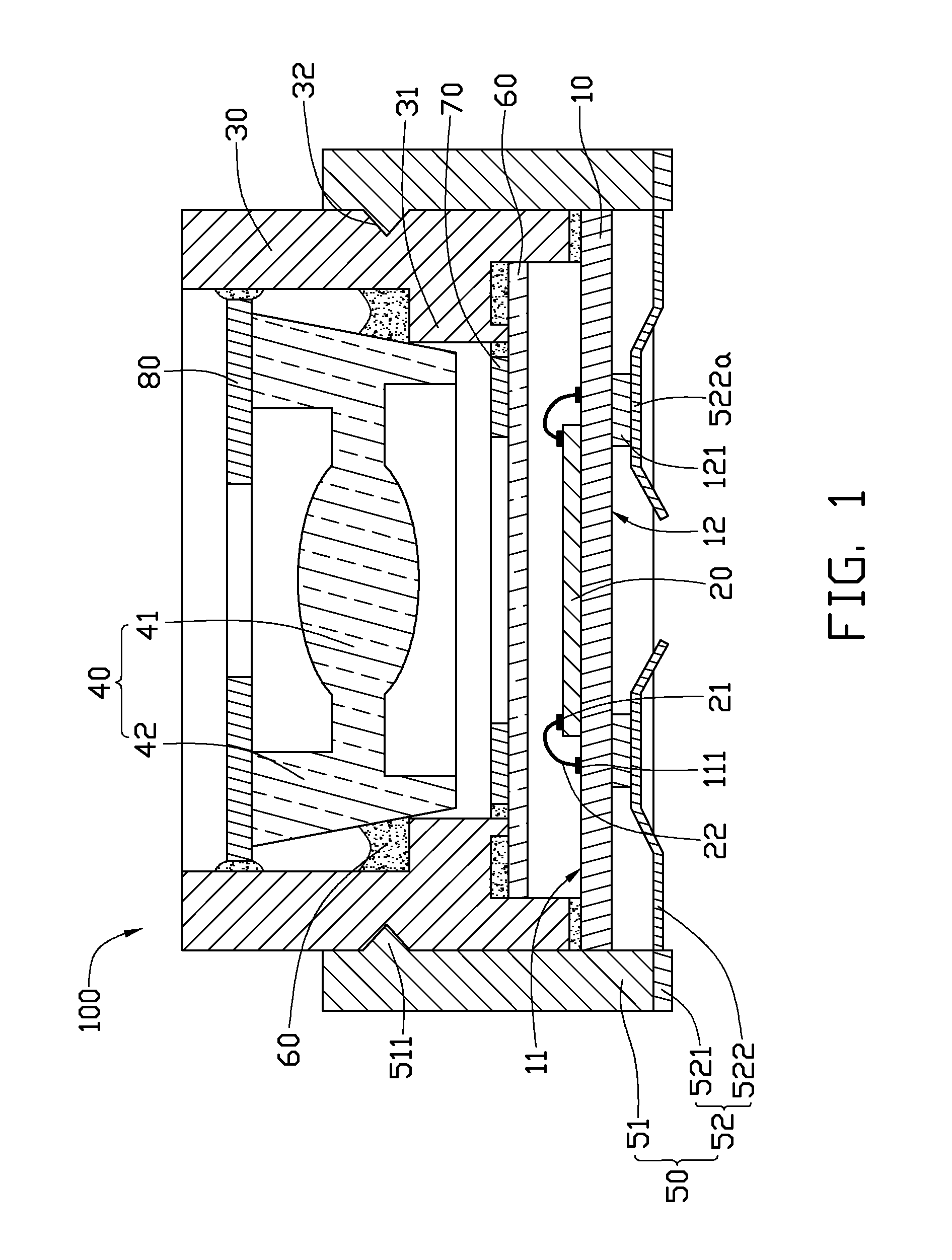
[0009]Referring to FIG. 1, an imaging module 100, according to a first exemplary embodiment, is shown. The imaging module 100 includes a substrate 10, an image sensor 20, a lens barrel 30, a lens 40, and a holder 50. The image sensor 20 is fixed on the substrate 10. The lens 40 is received in the lens barrel 30. The substrate 10 is fixed on an end of the lens barrel 30. The lens barrel 30 is partially inserted into the holder 50.

[0010]The substrate 10 includes a first surface 11 and a second surface 12 at opposite sides thereof. The substrate 10 includes a plurality of first soldering pads 111 formed on the first surface 11, and a plurality of first connecting portions 121 formed on the second surface 12. Each first soldering pad 111 is electrically connected to a corresponding first connecting portion 121.

[0011]The image sensor 20 is fixed on the first surface 11. The image sensor 20 includes a plurality of second soldering pads 21 each connected to one first soldering pad 111 usin...


PUM


Abstract

An exemplary imaging module includes a substrate, an image sensor, a lens barrel, a lens, and a holder. The image sensor is fixed on the substrate, the lens barrel is connected to the substrate to enclose the image sensor, the lens is received in the lens barrel, and the holder is connected to the lens barrel and partially receives the lens barrel therein. The lens barrel includes an elastic protruding portion protruding from the inner surface thereof. The inner surface of the protruding portion elastically abuts a side surface of the lens.

Description

BACKGROUND[0001]1. Technical Field[0002]The present disclosure relates to imaging modules, and particularly relates to an optical imaging module with a fixed-focus lens.[0003]2. Description of Related Art[0004]With the ongoing progress of imaging technology, imaging modules are becoming more and more compact. An imaging module often employs a fixed-focus lens. In assembly of the imaging module, the fixed-focus lens is positioned such that the focus of the fixed-focus lens is on an imaging surface of an image sensor of the imaging module. Then the fixed-focus lens is fixed in position relative to the image sensor. Currently, the position of the fixed-focus lens is adjusted by screwing. However, it is difficult to make a screw thread on the imaging module, and the need for a screw thread increases the cost of the imaging module. In addition, the shape of the fixed-focus lens, and associated optical components such as a lens barrel, must be circular. Therefore, design options for these...

Claims


Application Information

Patent Timeline
Patent Type & Authority Applications(United States)
IPC IPC(8): H04N5/225G02B7/02G03B11/04
CPCG02B7/022H04N5/2257H04N5/2254G02B7/025H04N23/57H04N23/55
Inventor CHANG, JEN-TSORNG
Owner HON HAI PRECISION IND CO LTD
Why Eureka
Try Eureka