Developer container and image forming device

a technology of developing containers and forming devices, which is applied in the direction of instruments, electrographic process devices, optics, etc., can solve the problems of waste toner leaking through the gap between the recovery port and the discharging section, and achieve the effect of reliably recovering waste toner and preventing waste toner from leaking

Active Publication Date: 2011-03-31
BROTHER KOGYO KK
View PDF17 Cites 26 Cited by
  • Summary
  • Abstract
  • Description
  • Claims
  • Application Information

AI Technical Summary

Benefits of technology

In view of the foregoing, it is an object of the invention to provide a developer container capable of recovering waste toner reliably and preventing the waste toner from leaking.

Problems solved by technology

Hence, if vibrations occur due to driving of the photosensitive drum during an image forming operation, the vibrations may be transmitted to the toner discharging section fitted in the recovery port of the toner cartridge, causing the toner discharging section to be damaged or causing waste toner to leak through a gap between the recovery port and the toner discharging section.

Method used


Image

  • Developer container and image forming device
  • Developer container and image forming device
  • Developer container and image forming device

Examples


Embodiment Construction

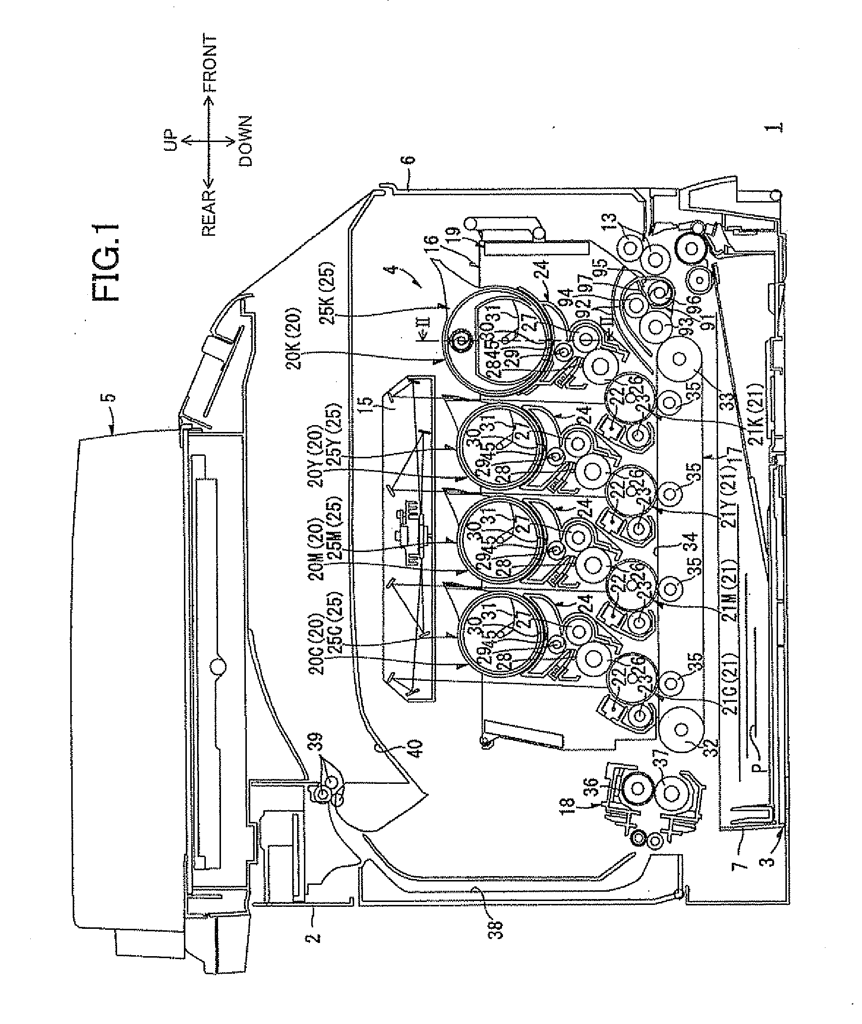
As shown in FIG. 1, a printer 1 is a horizontal direct tandem type color laser printer. The printer 1 includes a main casing 2 and, within the main casing 2, a feeding unit 3 for feeding sheets of paper P to be printed, an image-forming unit 4 for forming images on the sheets of paper P conveyed from the feeding unit 3, and an image-reading unit 5 for reading image data from original documents. Thus, the printer 1 is a multifunction peripheral that is integrally provided with the image-forming unit 4 and image-reading unit 5.

The main casing 2 has a box shape that is substantially rectangular in a side view. The feeding unit 3, image-forming unit 4, and image-reading unit 5 are accommodated in the main casing 2. A front cover 6 is provided on one side wall of the main casing 2 for exposing the inside of the main casing 2 in order to mount or remove a process unit 16 described later.

In the following description, the side of the printer 1 on which the front cover 6 is provided (right s...


PUM


Abstract

A developer container includes a casing, a conveying member, a conveying-member accommodating unit, and a supporting member. The casing extends in a longitudinal direction and has a developer accommodating chamber and a waste-developer accommodating chamber and a first opening. The developer accommodating chamber accommodates developer therein. The waste-developer accommodating chamber accommodates waste developer therein. The first opening provides fluid communication between the developer accommodating chamber and outside of the casing. The casing has a first end and a second end opposite the first end in the longitudinal direction. The conveying member is configured to convey the waste developer in a conveying direction defined to be directed from the first end to the second end. The conveying-member accommodating unit is configured to accommodate the conveying member therein. The conveying-member accommodating unit has an upstream end portion and a downstream end portion in the conveying direction. The conveying-member accommodating unit has a second opening and a third opening. The second opening is provided in the upstream end portion and provides fluid communication between inside of the conveying-member accommodating unit and outside of the conveying-member accommodating unit. The third opening provides fluid communication between the inside of the conveying-member accommodating unit and the waste-developer accommodating chamber. The supporting member is provided on the casing. The supporting member supports the conveying-member accommodating unit such that the conveying-member accommodating unit is movable in directions perpendicular to the longitudinal direction relative to the casing.

Description

CROSS REFERENCE TO RELATED APPLICATIONThis application claims priority from Japanese Patent Application No. 2009-227952 filed Sep. 30, 2009. The entire content of the priority application is incorporated herein by reference.TECHNICAL FIELDThe present invention relates to a developer container and an image forming device.BACKGROUNDOne electrophotographic color printer well known in the art is a tandem color laser printer equipped with four photosensitive drums to support the use of toner in the four colors yellow, magenta, cyan, and black. Each of four photosensitive drums corresponds to one of four developer cartridges for supplying developer to the corresponding photosensitive drum. One such tandem color laser printer includes a developing unit having a toner cartridge for accommodating toner for each color as developer cartridge. The toner cartridge has a toner accommodating section for accommodating fresh toner and a waste-toner accommodating section for accommodating waste toner...

Claims


Application Information

Patent Timeline
Patent Type & Authority Applications(United States)
IPC IPC(8): G03G15/08
CPCG03G21/12G03G21/105G03G15/0865G03G15/0868G03G15/0832G03G15/0886
Inventor SATO, SHOUGO
Owner BROTHER KOGYO KK
Why Eureka
Try Eureka