Method for forming a staple

a technology of staples and staples, which is applied in the field of surgical staples, can solve the problems of inability to adjust the formed height of staples and the inability to move the needl

Inactive Publication Date: 2011-04-14
CILAG GMBH INT +1
View PDF101 Cites 1637 Cited by
  • Summary
  • Abstract
  • Description
  • Claims
  • Application Information

AI Technical Summary

Problems solved by technology

In typical stapling instruments, however, the anvil is unmovable relative to the staple cartridge once

Method used


Image

  • Method for forming a staple
  • Method for forming a staple
  • Method for forming a staple

Examples


example 1

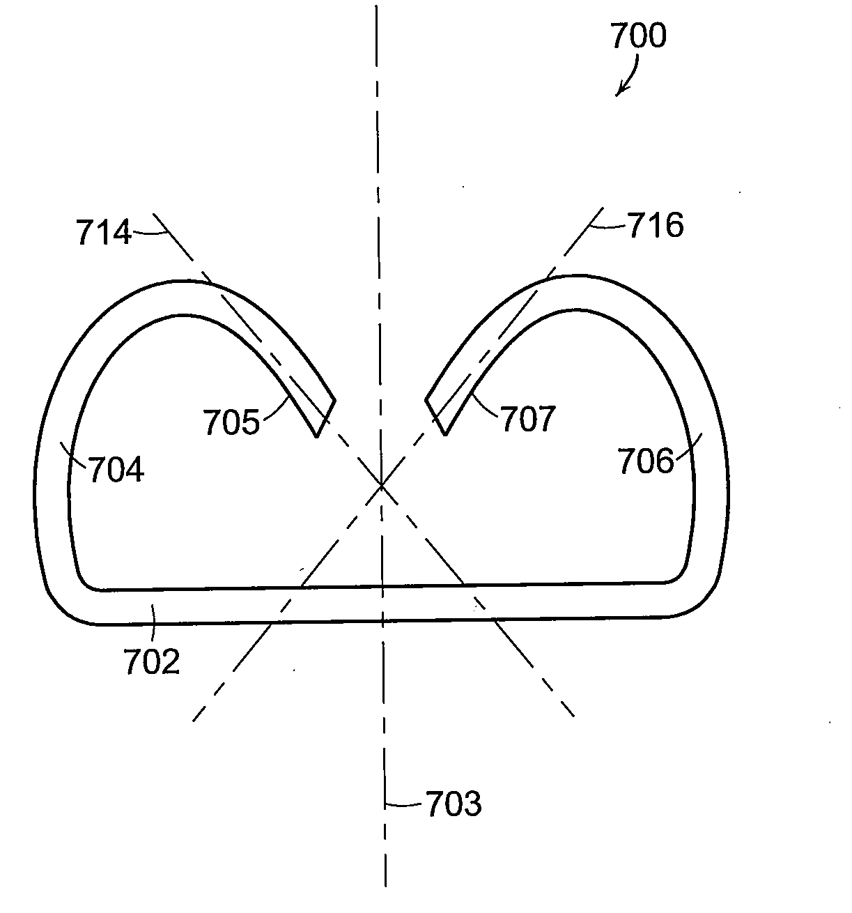
[0151]A surgical staple can be deformed such that:

First LegSecond LegCrosses the midline (FIG. 50)Crosses the midline (FIG. 50)Extends in-plane, or substantially in-Extends out of plane with theplane, with the base (FIG. 58)base (FIG. 52)The end extends in a non-The end extends in a non-perpendicular direction with theperpendicular direction with thebaseline (FIG. 50)baseline (FIG. 50)

example 2

[0152]A surgical staple can be deformed such that:

First LegSecond LegCrosses the midline (FIG. 50)Crosses the midline (FIG. 50)Extends out of plane with theExtends out of plane with thebase (FIG. 52) to the same sidebase (FIG. 52) to the same sideof the base as the second leg,of the base as the first leg,the distance X1 being differentthe distance X1 being differentthan X2 (FIG. 52A)than X2 (FIG. 52A)The end extends in a non-The end extends in a non-perpendicular direction with theperpendicular direction with thebaseline (FIG. 50)baseline (FIG. 50)

example 3

[0153]A surgical staple can be deformed such that:

First LegSecond LegDoes not cross the midlineDoes not cross the midline(FIG. 57)(FIG. 57)Extends out of plane with theExtends out of plane with thebase (FIG. 52) to a first sidebase (FIG. 52) to a second sideof the base, the distance X1of the base, the distance X1being different than X2 (FIG. 52A)being different than X2 (FIG. 52A)The end extends in a non-The end extends in a non-perpendicular direction with theperpendicular direction with thebaseline (FIG. 50)baseline (FIG. 50)


PUM

PropertyMeasurementUnit
Angleaaaaaaaaaa
Angleaaaaaaaaaa
Angleaaaaaaaaaa

Abstract

A method for deforming a staple comprising a base, a first staple leg, and a second staple leg, wherein the base, the first staple leg, and the second staple leg are positioned within a common plane prior to being deformed, the method comprising positioning the first staple leg within a first cup of a staple pocket, the first cup comprising a first inner surface, applying a first compressive force to an end of the first staple leg to bend the first staple leg toward the base and the second staple leg, contacting the first inner surface with the end of the first staple leg to bend the end of the first staple leg toward a first side of the base, and deforming the first staple leg such that the end of the first staple leg crosses a mid-line of the staple defined between the first staple leg and the second staple leg.

Description

CROSS-REFERENCE TO RELATED APPLICATION[0001]This non-provisional patent application claims the benefit under 35 U.S.C. §119(e) of U.S. Provisional Patent Application No. 61 / 250,377, entitled SURGICAL STAPLER, which was filed on Oct. 9, 2009, the entire disclosure of which is incorporated by reference herein.BACKGROUND[0002]i. Technical Field[0003]The present invention relates to stapling instruments and, in various embodiments, to a surgical stapling instrument for producing one or more rows of staples.[0004]ii. Background of the Related Art[0005]In recent years, there has been an increasing tendency for surgeons to use stapling instruments to suture body tissues such as a lung, an esophagus, a stomach, a duodenum and / or other organs in the intestinal tract. The use of an appropriate stapling instrument in many instances may perform a better job in less time and simplify previously difficult surgical procedures such as gastrointestinal anastomoses. Previous linear two and four row c...

Claims


Application Information

Patent Timeline
IPC IPC(8): A61B17/064A61B17/068
CPCA61B17/0644A61B17/0686A61B2017/07285A61B2017/07264A61B17/07207
Inventor BEDI, JAMES J.DUNKI-JACOBS, ADAM R.
Owner CILAG GMBH INT
Why Eureka
Try Eureka