Illumination apparatus

a technology of illumination apparatus and slitting plate, which is applied in the direction of lighting and heating apparatus, lighting support devices, instruments, etc., can solve the problems of non-uniform vertical luminance of images and vertical unsymmetric light distribution

Active Publication Date: 2011-04-21
NIKON CORP
View PDF0 Cites 3 Cited by
  • Summary
  • Abstract
  • Description
  • Claims
  • Application Information

AI Technical Summary

Benefits of technology

[0014]According to the present invention, it is possible to provide an illumination apparatus that can make the light distribution vertically symmetrical irrespective of the amount of the movement of the light source.

Problems solved by technology

When the position of the light source deviates greatly from the optical axis in this way, the light distribution becomes vertically unsymmetrical, and the vertical luminance of the image becomes non-uniform.

Method used


Image

  • Illumination apparatus
  • Illumination apparatus
  • Illumination apparatus

Examples


first embodiment

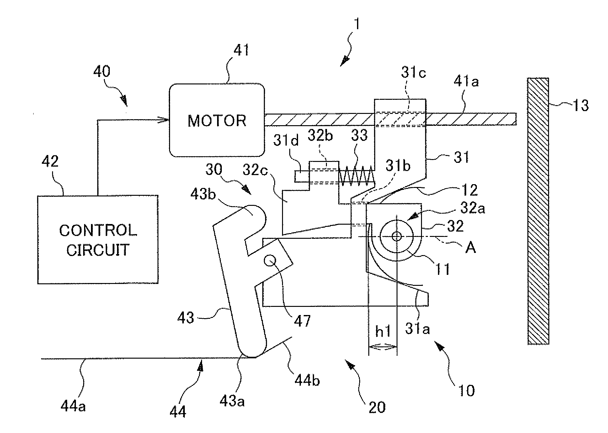
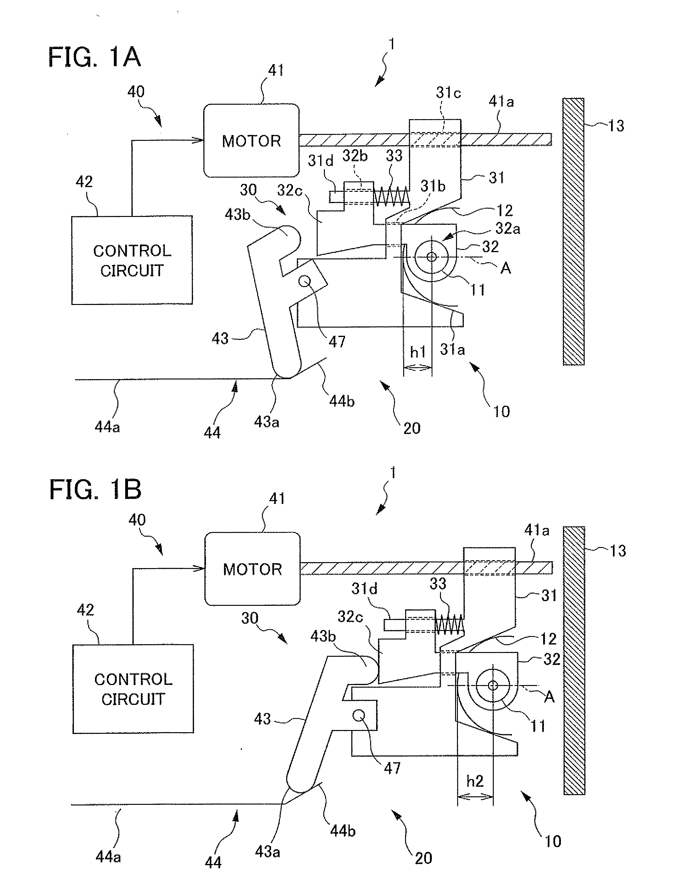
[0023]FIGS. 1A and 1B are block diagrams showing an illumination apparatus 1 according to a first embodiment. FIG. 1A shows a configuration when a zoom mechanism 20 is positioned to a telephoto side, and FIG. 1B shows a configuration when positioned to a wide-angle side.

[0024]The illumination apparatus 1 according to the present embodiment is configured with a light source unit 10 and a zoom mechanism 20. The light source unit 10 includes a xenon tube 11, a reflector 12, and diffuser 13. The xenon tube 11 is a light source that generates illumination light, and is a light emission tube that illuminates by way of electric power being supplied from a capacitor, which is not illustrated, to emit illumination light. It should be noted that the light source is not limited to a xenon tube, and may be a light emitting diode, for example. In addition, illustrations and explanations for a boosting circuit for causing the xenon tube 11 to illuminate and the like are omitted. Moreover, the ref...

second embodiment

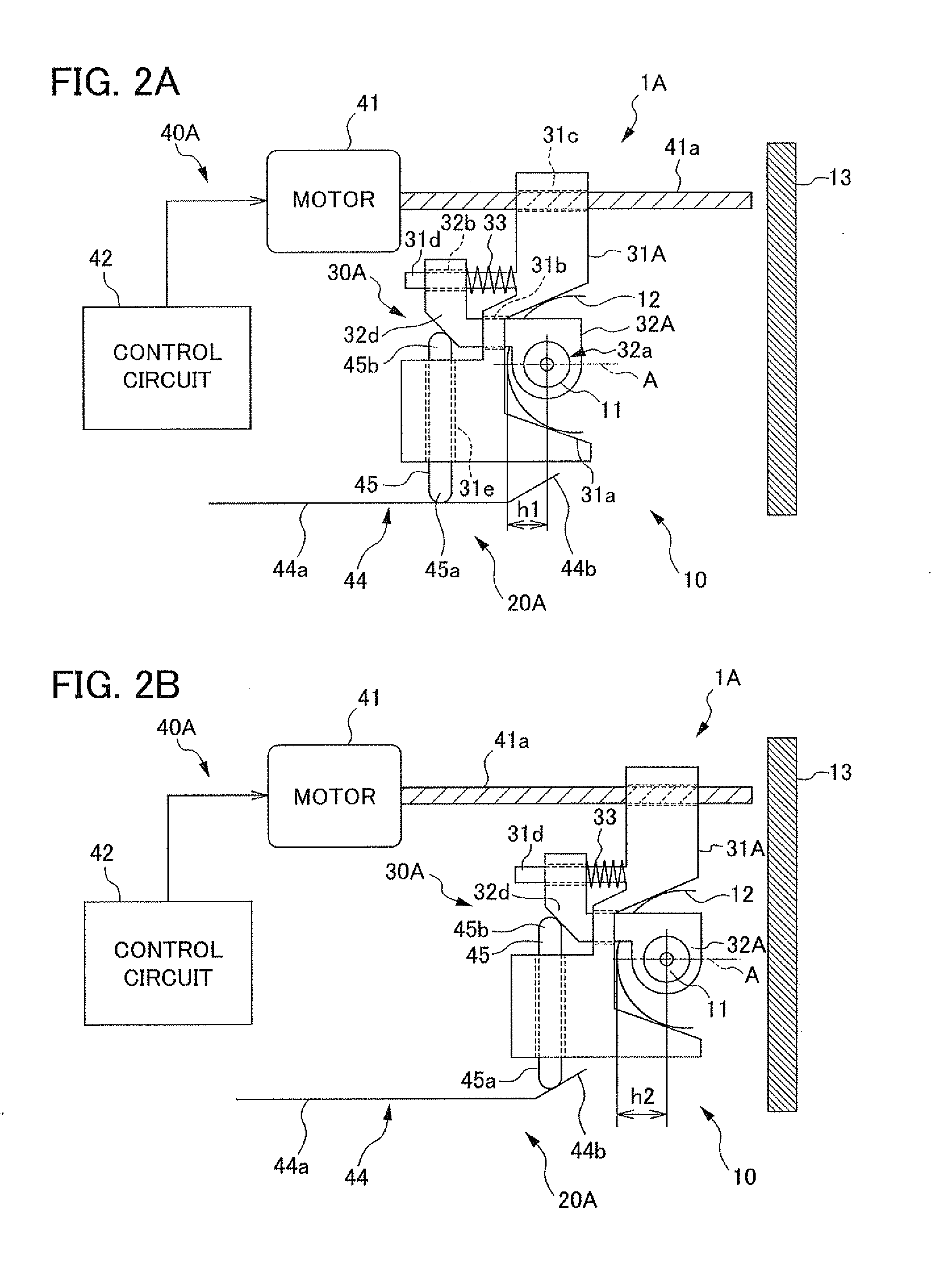
[0044]FIG. 2 is a block diagram of an illumination apparatus 1A according to a second embodiment. FIG. 2A shows a configuration when a zoom mechanism 20A is positioned to a telephoto side, and FIG.2 shows a configuration when positioned to a wide-angle side. Hereinafter, for equivalent parts to the first embodiment, the same reference symbols are assigned, and explanations are omitted.

[0045]The zoom mechanism 20A of the present embodiment is configured by a light source retaining portion 30A and a light source drive unit 40A. The light source retaining portion 30A includes a reflector holder 31A and a xenon tube holder 32A. The reflector holder 31A includes a reflector retaining portion 31a, reflector holder engaging portion 31b, drive shaft engaging portion 31c, straight guide member 31d, and drive pin engaging portion 31e. The drive pin engaging portion 31e is a through-hole portion through which a drive pin 45 described later is inserted.

[0046]The xenon tube holder 32A includes a...

third embodiment

[0057]FIG. 3 is a block diagram of an illumination apparatus according to a third embodiment. FIG. 3A shows a configuration when a zoom mechanism 20B is positioned to a telephoto side, and FIG. 3B shows a configuration when positioned to a wide-angle side. Hereinafter, for equivalent parts to the first embodiment, the same reference symbols are assigned, and explanations are omitted.

[0058]A zoom mechanism 20B of the present embodiment is configured by a light source retaining portion 30B and a light source drive unit 40B. The light source retaining portion 30B includes a reflector holder 31B and a xenon tube holder 32B. The reflector holder 31B includes a reflector retaining portion 31a, reflector holder engaging portion 31b, drive shaft engaging portion 31c, and second motor fixing portion 31f. The second motor fixing portion 31f is a part that fixes a second motor 46 described later.

[0059]The xenon tube holder 32B includes a holder portion 32a and a drive shaft engaging portion 32...


PUM


Abstract

An illumination apparatus including a light source that emits illumination light, an optical member that transmits the illumination light to externally project the illumination light, and a reflector that reflects illumination light from the light source towards the optical member, the device comprising: a drive device to drive the reflector and the light source to advance and retract in a substantially perpendicular direction relative to a light projection surface of the optical member; and a relative movement device to cause the light source to relatively move relative to the reflector in a process of driving to advance and retract by way of the drive device, wherein the relative movement device includes a straight guide member that causes the light source to move straight ahead in the substantially perpendicular direction relative to the reflector.

Description

[0001]The present application claims priority under 35 U.S.C. §119 to Japanese Patent Application No. 2009-241961 filed on Oct. 21, 2009. The content of the application is incorporated herein by reference in its entirety.BACKGROUND OF THE INVENTION[0002]1. Field of the Invention[0003]The present invention relates to an illumination apparatus.[0004]2. Description of the Related art[0005]Conventionally, an illumination apparatus exists that can automatically change its illumination angle to correspond to the focal length of the photographic lens. As a conventional example relating to this type of illumination apparatus, a flash device has been known that is made so that the light source is configured to freely swing on an optical axis direction with the axis of rotation as the pivot point, and the positional relationship between the light source and a reflector changes by way of this swinging (for example, Japanese Patent No. 3022295).SUMMARY OF THE INVENTION[0006]With the above-menti...

Claims


Application Information

Patent Timeline
Patent Type & Authority Applications(United States)
IPC IPC(8): F21V7/00
CPCG03B2215/0528G03B15/02
Inventor YANAI, JUNICHI
Owner NIKON CORP
Why Eureka
Try Eureka