
Method for the Operation of a Compressor of a Gas Turbine With Evaporative Cooling of the Compressor Induction Air

Inactive Publication Date: 2007-04-19
ANSALDO ENERGIA IP UK LTD
View PDF2 Cites 1 Cited by
  • Summary
  • Abstract
  • Description
  • Claims
  • Application Information

AI Technical Summary

Benefits of technology

[0014] Preferably, such a shutting down of the evaporative cooling is also undertaken if the pressure of the medium which is supplied for the evaporative cooling, especially water, exceeds or falls below defined, predeterminable limiting values. Preferably, the shutting down is undertaken when the pressure in the feed line drops below 120*105 Pa (120 bar), or rises above 180*105 Pa (180 bar). In a further development, this shutting down also takes place if the mass flow of the medium which is supplied for evaporation differs by more than 5% of a predetermined rated mass flow.
[0015] A further aspe

Problems solved by technology

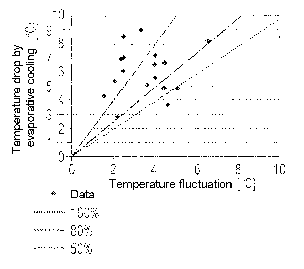
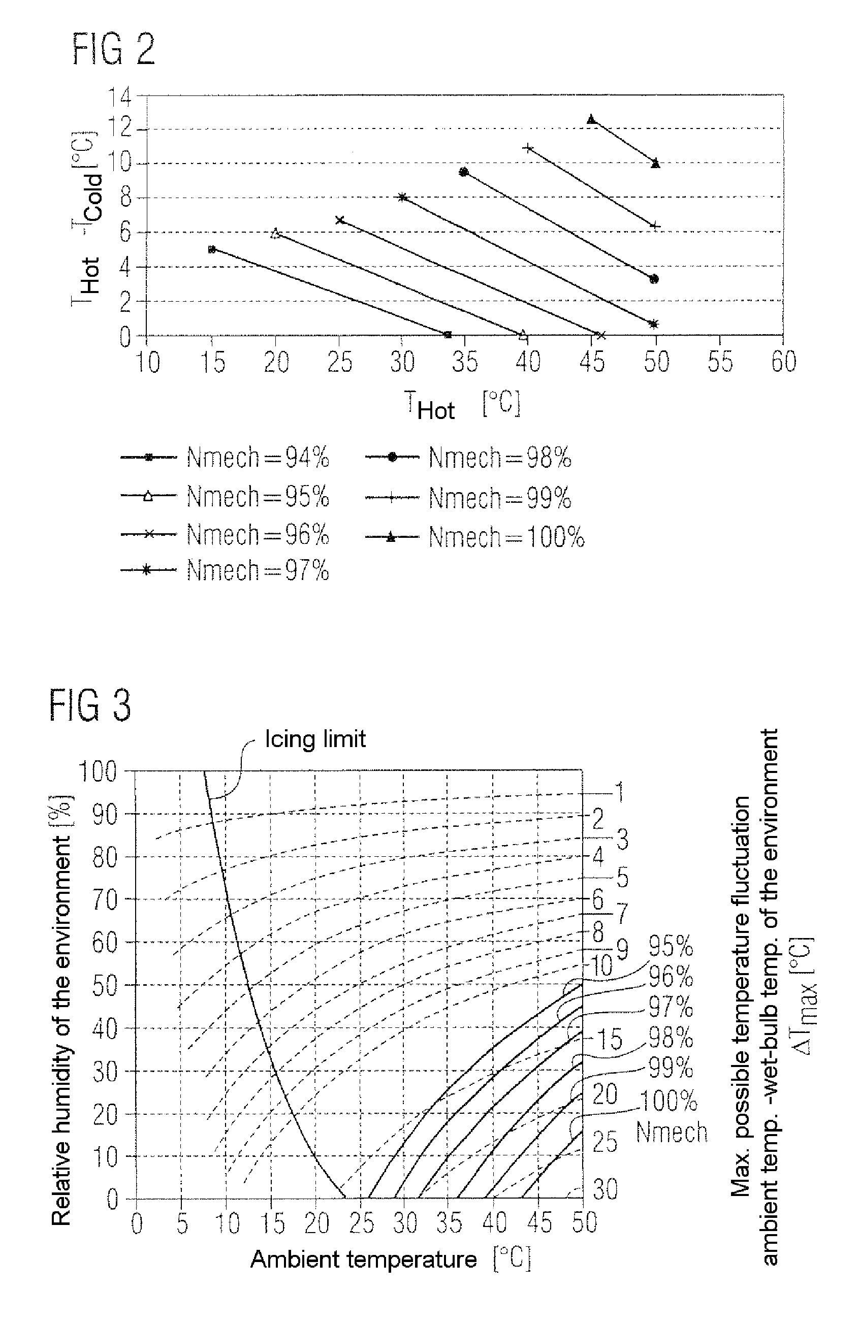
This limited operating range results from the determining of temperature fluctuations which occur in the worst case from the maximum possible temperature drop (or a fractional part of it) by the evaporative cooling at different environmental conditions.
By this procedure, the operating line of the compressor is limited, therefore, in dependence upon environmental conditions and RPM.

Method used


Image

  • Method for the Operation of a Compressor of a Gas Turbine With Evaporative Cooling of the Compressor Induction Air
  • Method for the Operation of a Compressor of a Gas Turbine With Evaporative Cooling of the Compressor Induction Air
  • Method for the Operation of a Compressor of a Gas Turbine With Evaporative Cooling of the Compressor Induction Air

Examples


Embodiment Construction

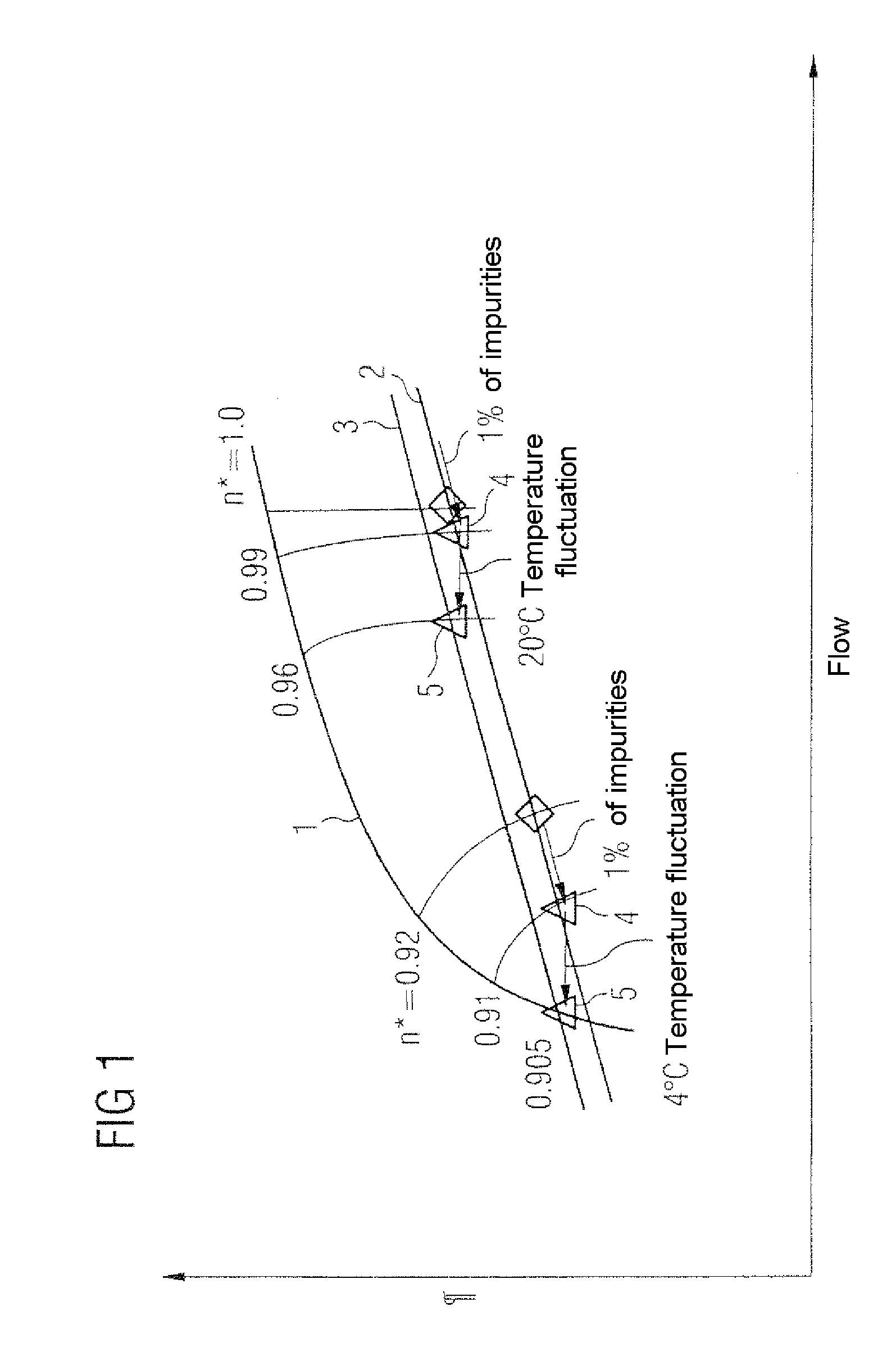
[0023]FIG. 1 exemplarily shows a map of a compressor of a gas turbine, in which are drawn the surge limit 1, the undisturbed operating line 2 and also the operating line 3 which is shifted by temperature fluctuations. Furthermore, the lines of constant RPM of the compressor at different RPMs n* (as a fractional part of the rated RPM) are visible. Such a method of presentation is familiar to a person skilled in the art. In this connection, an operating characteristic, based on an operating point 4, is shown in the right hand section of the figure, in which the operating point by 1% contamination on the operating line 2 is shifted first to a somewhat reduced flow, and then by temperature fluctuations with a fluctuation amplitude of 20° C. is shifted onto an operating point 5 on the shifted operating line 3. From the map, it is evident that in this operating range there is no risk of surging since there is still a sufficient distance from the surge limit 1.

[0024] In a region of reduce...


PUM


Abstract

In a method of operating a compressor of a gas turbine, where compressor air sucked in from the environment is cooled down by evaporation cooling before entering the compressor, before starting operation of the compressor, maximum possible temperature drops which could be achieved by evaporation cooling are determined dependent on different ambient conditions and / or are provided as a data set. These temperature drops are correlated with a compressor map containing maximum temperature distortions at different ambient conditions and different rotation frequencies of the compressor which have to be met in order to avoid pumping. The evaporation cooling is then only operated when current ambient condition result in a maximum possible temperature drop from which a predetermined fraction of between 50% and 100% does not exceed the maximum distortion which can be taken from the compressor map for these ambient conditions and the current rotation frequency of the compressor. Safe operation of the compressor can be achieved without the need or monitoring temperature distortions in the sucked in air stream.

Description

[0001] This application is a Continuation of, and claims priority under 35 U.S.C. § 120 to, International application number PCT / EP2005 / 052709, filed 13 Jun. 2005, and claims priority therethrough under 35 U.S.C. § 119 to Swiss application number 01045 / 04, filed 22 Jun. 2004, the entireties of which are incorporated by reference herein.BACKGROUND OF THE INVENTION [0002] 1. Field of the Invention [0003] The invention under consideration relates to a method for operation of a compressor of a gas turbine, in which compressor air, which is inducted from the environment, is cooled by means of evaporative cooling before entry into the compressor. [0004] During the operation of gas turbines, air which is inducted from the environment, is compressed in a compressor and fed to the gas turbine process. To increase the efficiency of the gas turbine it is known to additionally cool the inducted compressor air before entry into the compressor. This cooling takes place in many cases by injection ...

Claims


Application Information

Patent Timeline
IPC IPC(8): F02C3/30F02C7/143F04D27/02F04D29/58
CPCF02C7/1435
Inventor CATALDI, GIOVANNIFAEHNDRICH, CHRISTIANMATZ, CHARLES
Owner ANSALDO ENERGIA IP UK LTD
Learn More